
December 4, 2018
| ANSI/UL 1479 (ASTM E814) | CAN/ULC S115 |
|---|---|
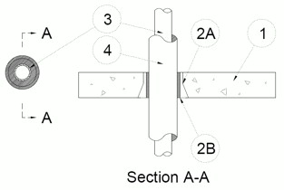
1.Floor or Wall Assembly — Min 4-1/2 in.(114 mm) thick reinforced lightweight or normal weight (100-150 pcf or 1600-24000 kg/m3) concrete. Wall may also be constructed of any UL Classified Concrete Blocks*.
See Concrete Blocks (CAZT) category in the Fire Resistance Directory for names of manufacturers.
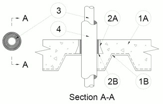
1A.Floor Assembly — Not shown) As an alternate to item 1, The fire-rated unprotected concrete and steel deck floor assembly shall be constructed of the materials and in the manner specified in the individual D900 Series designs in the UL Fire Resistance Directory and as summarized below:
A.Concrete — Min 4-1/2 in. (114 mm) thick reinforced lightweight or normal weight (100-150 pcf or 1600-2400 kg/m3) concrete.B.Steel Floor and Form Units* — Composite or non-composite max 3 in. (76 mm) deep fluted galv units as specified in the individual Floor-Ceiling design.
2.Firestop System — The firestop system shall consist of the following:
A.Firestop Device* — Cast in place firestop device permanently embedded during concrete placement in accordance with accompanying installation instructions. The device may project up to a max of 3-1/2 in. (89 mm) above top surface of floor or trimmed flush with top surface of floor in min 4-1/2 in. (114 mm) thick floors. The device shall extend min flush with floor surface up to a max of 5-1/2 in. (140 mm) above top surface of floor in min 2-1/2 in. (64 mm) thick floors. The devices are provided in sizes, nom 2, 3, 4 and 6 in. (51, 76, 102 and 152 mm) diam sizes.
RECTORSEAL — Metacaulk Cast-in-Place DeviceB.Packing Material — Min 4 in. (102 mm) thickness of min 4 pcf (64 kg/m3) mineral wool batt insulation firmly packed into the annular space as a permanent form. The packing material is to be installed flush with the top surface of the floor or recessed from the top surface of the device to accommodate the required thickness of caulk (Item 5).
3.Through Penetrants — One metallic pipe or tubing to be installed concentrically within the firestop system. Pipe or tubing to be rigidly supported on both sides of floor or wall assembly. The following type and size of metallic pipe or tubing may be used:
A.Copper Pipe — Nom 4 in. (102 mm) diam (or smaller) Regular (or heavier) copper pipe.B.Copper Tubing — Nom 4 in. (102 mm) diam (or smaller) Type L (or heavier) copper tubing.C.Steel Pipe — Nom 4 in. (102 mm) diam (or smaller) schedule 10 or heaver steel pipe.
4.Pipe Coverings* — All Penetrants shall be provided with one of the following pipe coverings.
A.Tube Insulation-Plastics+ — Max 1 in. (25 mm) thick acrylonitrile butadiene/polyvinyl chloride (AB/PVC) flexible foam furnished In the form of tubing.See Plastics (QMFZ2) category in the Plastics Recognized Component Directory for names of manufacturers. Any Recognized Component tube insulation material meeting the above specifications and having a UL 94 Flammability Classification of 94-5A may be used.
B.Pipe and Equipment Covering Materials* — Nom 1 in. (25 mm) thick hollow cylindrical heavy density glass fiber units jacketed on the outside with an all service jacket. Longitudinal joints sealed with metal fasteners or factory-applied self-sealing lap tape. Transverse joints secured with metal fasteners or with butt tape supplied with the product.See Pipe and Equipment Covering - Materials* (BRGU) category in the Building Materials Directory for names of manufacturers. Any pipe covering material meeting the above specifications and bearing the UL Classification Marking with a Flame Spread Index of 25 or less and a Smoke Developed Index of 50 or less may be used.
2-3/4 Hr T Rating only applies when fiber glass insulation (Item 4B) is used.
4A.PVC Jacket+ — (Optional) An additional PVC jacketing (Item 4,B), supplied in sheet form, shall be tightly wrapped around the all service jacket on the pipe covering with the longitudinal seam continuously sealed using the adhesive supplied with the jacket. The jacket is to be nom 48 in. (1219 mm) wide by nom 20 or 30 mil (0.5 or 0.8 mm) thick. The jacket shall be installed at a point 36 in. (914 mm) to 40 in. (1016 mm) above the top surface of the floor assembly and shall extend downward into and/or through the opening.
See Plastics (QMFZ2) category in the Plastics Recognized Component Directory for names of manufacturers. Any Recognized Component tube insulation material meeting the above specifications and having a UL 94 Flammability Classification of 94-5VA may be used.
The PVC jacket (Item 4A) is required for all fiberglass pipe coverings for the W Rating to apply.
5.Fill, Void or Cavity Material* — Caulk — (Optional, Not Shown) - Min 1/4 in. (6 mm) thickness of caulk for 2-in. (51 mm), 3 in. (76 mm) and 4 in. (102 mm) CIP devices and min 3/8 in. (10 mm) thickness of caulk for 6 in. (152 mm) CIP device. Caulk applied within device, flush with top surface of device.
RECTORSEAL — Metacaulk 835+ or Metacaulk 1200
W Rating and L Ratings apply only when Jacket (Item 4A), and (Item 5) sealant is used
+Bearing the UL Recognized Component Marking.