June 25, 2021
| ANSI/UL 1479 (ASTM E814) |
|---|
| F Rating — 2, 3 and 4 Hr (See Item 3) |
| T Rating — 0, 1, 2, 2-3/4, 3 or 4 Hr (See Item 2) |
| L Rating At Ambient — Less Than 1 CFM/device |
| L Rating At 400°F — Less Than 1 CFM/device |
| W Rating — Class 1 (See Item 5) |
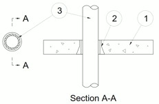
1.Floor Assembly — (Config A) Min 4-1/2 in. (114 mm) thick reinforced lightweight or normal weight (100-150 pcf or 1600-2400 kg/m3) concrete.
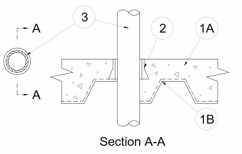
1A.Floor Assembly — (Config B) As an alternate to Item 1. The fire-rated unprotected concrete and steel floor assembly shall be constructed of the materials and in the manner specified in the individual D900 Series designs in the UL Fire Resistance Directory and as summarized below:A.Concrete — Min 4-1/2 in. (114 mm) thick reinforced lightweight or normal weight (100-150 pcf or 1600-2400 kg/m3) concrete.B.Steel Floor and Form Units* — Composite or noncomposite max 3 in. (76 mm) deep fluted galv units as specified in the individual Floor-Ceiling design.
2.Firestop Devices* — Cast in place firestop device permanently embedded during concrete placement in accordance with accompanying installation instructions. The device shall be trimmed flush with the top surface of the floor or project above it max 5-1/2 in. (140 mm). The devices are provided in nom 2, 3, 4 and 6 in. (51, 76, 102 and 152 mm) diam sizes.
RECTORSEAL — Metacaulk Cast-in-Place Device
3.
Through Penetrants — One nonmetallic pipe or conduit installed within the firestop system. Pipe or conduit to be rigidly supported on both sides of floor assembly. Max nominal 3 in. (76 mm) ABS (Item 3D) diameter. Max Nominal 2 in. (51 mm) PEX(3F) Diameter. Max nominal 6 in. (152 mm) diameter for all other penetrants. The nominal Firestop Device (Item 2) size shall be the same as the nominal penetrant size. A min 1/2 in. (13 mm) annular space shall be maintained between the penetrant and the sidewall of the device. The following types of nonmetallic pipes, tubes or conduits may be used:
A.Polyvinyl Chloride (PVC) Pipe — Schedule 40 solid core PVC or cellular core PVC (ccPVC) pipe for use in closed (process or supply) or vented (drain, waste or vent) piping systems.B.Rigid Nonmetallic Conduit (RNC)+ — Schedule 40 PVC conduit installed in accordance with the National Electrical Code (NFPA No. 70).C.Chlorinated Polyvinyl Chloride (CPVC) Pipe — SDR11,13.5 or 21 CPVC pipe for use in closed (process or supply) piping systems.D.Acrylonitrile Butadiene Styrene (ABS) Pipe — Schedule 40 solid core ABS or cellular core ABS (ccABS) pipe for use in closed (process or supply) or vented (drain, waste or vent) piping systems. Limited for use with nom 2 in. (51 mm) and 3 in. (76 mm) devices (Item 2).E. Polyvinyl Chloride (PVC-XFR) Pipe
— Schedule 40 solid core PVC XFR for use in closed (process or supply) or vented (drain, waste or vent) piping systems.F. Crosslinked polyethylene (PEX) Tubing
— SDR 9 PEX tubing for use in closed (process or supply) or vented (drain, waste or vent) piping system
Penetrant Item Sch or SDR Nom Diameter in. (mm) F- Rating hr T-Rating hr A, B, E
Sch 40
2, 3, 4 (51, 76, 102)
3
3
A
Sch 40
6 (152)
4
2-3/4
C, E
Sch 40, SDR 13.5
6 (152)
3
2-3/4
C
SDR 11
2 (51)
3
3
C
SDR 11
3, 4 (76, 102)
2
2
C
SDR 13.5
2, 3, 4,(51, 72, 102)
3
2-3/4
C
SDR 21
2 (51)
3
2-3/4
D
Sch 40
2 (51)
2
1
D
Sch 40
3 (76)
2
2
F
SDR 9
2 (51)
3
0
4.Packing Material — (Not shown) - When penetrant is less than nom 3 in. (76 mm) installed within the nom 4 in. (102 mm) device and less than nom 2 in. (51 mm) installed within the nom 2 in. (51 mm) device, a min 3 in. (76 mm) thickness of min 4 pcf (64 kg/m3) mineral wool batt insulation shall be firmly packed into the annular space between the penetrant and device as a permanent form. The packing material is to be recessed 1-1/2 in. (38 mm) below the top surface of the floor and extend upward a min of 1-1/2 in. (38 mm) above the top surface of the floor. When optional caulk (Item 5) is used, packing material to be recessed from top of device to accommodate the required thickness of caulk.
5.Fill, Void or Cavity Material* — Caulk — (Optional, Not Shown) - Min 1/4 in. (6 mm) thickness for 2, 3, and 4 in. (51, 76 and 102 mm) and min 3/8 in. (10 mm) thickness for 4 in. (102 mm) and 6 in. (152 mm) device (Item 2). Caulk applied within device to finish flush with top surface of device. The min thickness and packing material shall conform to the following table:
Caulk Minimum
Thickness
In., (mm)Device Size
In. (mm)Packing Material Metacaulk 835+ or Metacaulk 1200 1/4 (6) 2, 3, or 4 (51, 76 or 102) Min. 3 in. (76 mm) thickness of min. 4.0 pcf (64 kg/m3) mineral wool Metacaulk 835+ or Metacaulk 1200 3/8 (10) 6 (152) Min. 3 in. (76 mm) thickness of min. 4.0 pcf (64 kg/m3) mineral wool Metacaulk 150+ or Metacaulk 1200 1/2 (13) 2, 3, 4, or 6 (51, 76, 102 or 152) Foam backer rod Metacaulk 1000 1/2 (13) 2, 3, 4, or 6 (152) Min. 4 in. (102 mm) thickness of min. 4.0 pcf (64 kg/m3) mineral wool
RECTORSEAL — Metacaulk 150+, Metacaulk 835+, Metacaulk 1000 or Metacaulk 1200.
W Rating only applies when the optional caulk is used.