F-A-2049
June 3, 2002
June 3, 2002
F Rating — 2 Hr
T Rating — 1/4 Hr
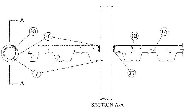
1.Floor Assembly — The fire-rated unprotected concrete and steel floor assembly shall be constructed of the material and in the manner specified in the individual D900 Series designs in the UL Fire Resistance Directory and as summarized below:
A.ConcreteMin 2-1/2 in. thick reinforced lightweight or normal weight (100-150 pcf) concrete.
B.Welded Wire Fabric 6 x 6 - W1.4 x W1.4
C.Steel Floor and form Units* Composite or noncomposite 3 in. deep fluted galv units as specified in the individual Floor-Ceiling design. Max diam of opening core-drilled through floor assembly is 6 in.
2.Through Penetrants — One nonmetallic pipe to be centered within the firestop system. The annular space between pipe and periphery of opening shall be nom 3/4 in. Pipe to be rigidly supported on both sides of floor assembly. The following types and sizes of nonmetallic pipes may be used:
A.Polyvinyl Chloride (PVC) Pipe — Nom 4 in. diam (or smaller) Schedule-40 cellular or solid core PVC pipe for use in closed (process or supply) or vented (drain, waste or vent) piping systems.B.Acrylonitrile Butadiene Styrene (ABS) Pipe — Nom 4 in. diam (or smaller) Schedule 40 cellular or solid core ABS pipe for use in closed (process or supply) piping systems.C.Chlorinated Polyvinyl Chloride (CPVC) Pipe — Nom 4 in. diam (or smaller) SDR 17 CPVC pipe for use in closed (process or supply) or vented (drain, waste or vent) piping systems.
3.Firestop System — The details of the firestop systems shall be as follows:
A.Steel Sleeve — (Optional - Not shown) — Nom 6 in. diam (or smaller) cylindrical sleeve formed from min 22 guage sheet steel. Sleeve is installed by coiling sheet steel to a diam smaller than the through opening and allowing it to uncoil. Sleeve shall have a min 1 in. overlap along longitudinal seam and shall be cast or grouted into floor assembly. The sleeve shall be installed flush with the valley of the fluted deck and may be flush with or project a max 2 in. above top surface of the floor.B.Fill Void or Cavity Materials* — Wrap Strip — Nom 1/4 in. thick by 2 in. wide intumescent wrap strip. The wrap strip is continuously wrapped around the outer circumference of the pipe three times and slid into the annular space. When multiple strips are used to achieve the required total length, the ends are butted end to end and held in place with aluminum tape. The bottom edge of the wrap strip shall be positioned 1/4 in. above the crests of the steel floor units.
RECTORSEAL — Metacaulk Wrap StripC.Fill, Void or Cavity Material* Caulk — Min 1/4 in. thickness of fill material applied within the annulus on the top surface of the wrap strip.
RECTORSEAL — Metacaulk 1000