June 24, 2020
| ANSI/UL1479 (ASTM E814) | CAN/ULC S115 |
|---|---|
System tested with a pressure differential of 2.5 Pa between the exposed and the unexposed surfaces with the higher pressure on the exposed side.
1.Floor Assembly — (Config B) The fire-rated concrete and fluted steel deck floor assembly shall be constructed of the materials and in the manner specified in the individual D900 Series designs in the UL Fire Resistance Directory and as summarized below:
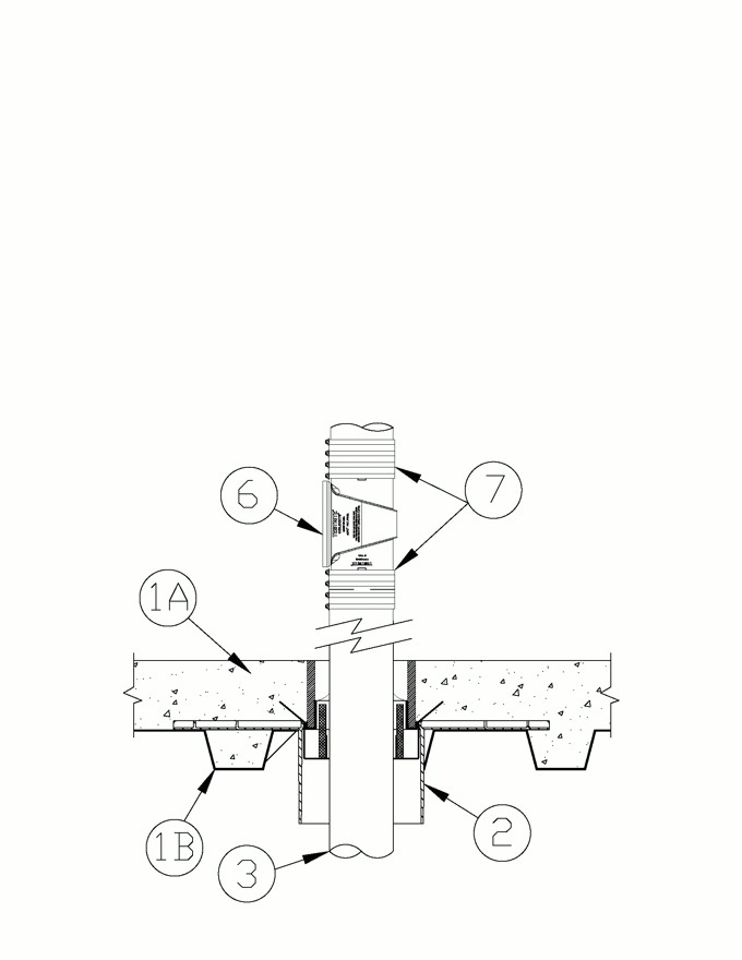
A.Concrete — Min 2-1/2 in. (64 mm) thick reinforced lightweight or normal weight (100-150 pcf or 1600-2400 kg/m3) concrete topping, as measured over crests of fluted floor units and over top of device base.B.Steel Floor and Form Units* — Composite or noncomposite nom 3 in. (76 mm) deep fluted galv units as specified in the individual Floor-Ceiling design. Diam of opening cut through fluted floor unit to be maximum 1/4 in. (6 mm) larger than outside diameter of bottom extension portion of firestop device base.
1.Floor Assembly — (Config A) — Min 4-1/2 in. (114 mm) thick reinforced lightweight or normal weight 100-150 pcf (1600-2400 kg/m3) concrete. Measured over the top of the device base.
Configuration A
2.Firestop Device* — Cast in place firestop device permanently embedded during concrete placement or grouted in concrete assembly in accordance with accompanying installation instructions. The device shall be installed flush with top and bottom surfaces of floor. Config A HFP devices and optional accessories (not shown) include sleeve extension, water module, deck adapter, aerator adapter and/or water dam installed in accordance with installation instructions. The devices are sized to accommodate the following nom pipe sizes:
Nom Pipe Diam in. (mm) Firestop Devices for Concrete Slab Firestop Devices for Fluted Deck (Not Shown) 1-1/4 to 2 (32 to 51) HFP-M2, HFP-M2B, HFP-P2, HFP-P2B add HFPCD2 2 to 3 (51 to 76) HFP-M3, HFP-M3B, HFP-P3, HFP-P3B add HFPCD3 3 to 4 (76 to 102) HFP-M4, HFP-M4B, HFP-P4, HFP-P4B add HFPCD4 4 to 5 (102 to 127) HFP-M5, HFP-M5B, HFP-P5, HFP-P5B add HFPCD5 5 to 6 (127 to 152) HFP-M6, HFP-M6B, HFP-P6, HFP-P6B add HFPCD6 When penetrant diameters are smaller than permitted in the table above, the use of Items 4B is required and Item 5 optional..
HOLDRITE —HydroFlame HFP-Mx, HFP-MxB, HFP-Px HFP-PxB
Configuration B
2.Firestop Device* — Cast in place firestop device permanently embedded during concrete placement or grouted in concrete assembly in accordance with accompanying installation instructions. The device shall be installed flush with top and bottom surfaces of floor. Optional accessory (not shown) aerator adapter installed in accordance with the installation instructions. The devices are sized to accommodate the following nom pipe sizes
Nom Pipe Diam in. (mm) Firestop Devices for Fluted Deck Firestop Devices for Concrete Slab (Not Shown) 1-1/4 to 2 (32 to 51) CD-PL-0200, CD-OPS-PL-0200, CD-OPS-MT-0200 WD-PL-0200, OPS-PL-0200, OPS-MT-0200 2 to 3 (51 to 76) CD-PL-0300, CD-OPS-PL-0300, CD-OPS-MT-0300 WD-PL-0300, OPS-PL-0300, OPS-MT-0300 3 to 4 (76 to 102) CD-PL-0400, CD-OPS-PL-0400, CD-OPS-MT-0400 WD-PL-0400, OPS-PL-0400, OPS-MT-0400 5 to 6 (127 to 152) CD-PL-0600, CD-OPS-PL-0600, CD-OPS-MT-0600 WD-PL-0600, OPS-PL-0600, OPS-MT-0600
HOLDRITE —HydroFlame CD-OPS-MT, CD-PL, CD-OPS-PL,WD-PL, OPS-PL, OPS-MT
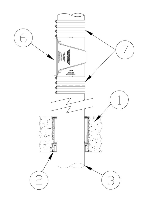
3.Through Penetrant — One metallic pipe to be installed within the firestop device. Pipe to be installed in accordance with firestop device installation instructions and rigidly supported on both sides of floor assembly. The following types of pipe, conduit or tubing may be used:
A.Iron Pipe — Nom 6 in. (152 mm) diam (or smaller) cast or ductile iron pipe.
4.Packing Material — (Optional. Not Shown) — Min 2 in. (51 mm) depth of min 4 pcf (64 kg/m3) mineral wool batt insulation tightly-packed into annular space between penetrant and device, flush with the top surface of the floor. When optional sealant (Item 5) is used, top surface of packing material to be recessed min 1/4 in. (6 mm) from top surface of floor.
4A.Packing Material — (Optional instead of 4, Not Shown) — Foam backer rod firmly packed into opening as a permanent form. Packing material to be recessed from top surface of floor as required to accommodate the required thickness of fill material.
4B.Packing Material — (Optional instead of Item 4, Not Shown) — For Configuration A only. When penetrant diameters are smaller than the device size range in the table above, Min. 3-3/4 in. depth from floor surface or to fullest extent possible to top of inner seal of min 4 pcf (64 kg/m3) mineral wool batt insulation tightly-packed into annular space between penetrant and device, flush with the top surface of the floor. When optional sealant (Item 5) is used, top surface of packing material to be recessed min 1/4 in. (6 mm) from top surface of floor.
5.Fill, Void or Cavity Material* — Sealant — (Optional, Not Shown) — Min 1/4 in. (6 mm) thickness of sealant applied within the annulus, flush with the top surface of floor. A Min 1/2 in. (13 mm) thickness of sealant applied within the annulus, flush with the top surface of floor to attain W-Rating. Conf B (Only), Sealant to lap min 1/2 in. (13 mm) onto top surface of concrete around perimeter of firestop device. As an alternate when sealant is optional 100% silicone sealant can be used.For Configuration A (ONLY), the W Rating and L Ratings apply according to the Table below.
Device size Iron (IPS) Diam in. (mm) W RATING L Rating HFP-x2, HFP-x2B 1-1/4 to 2 (32 to 51) YES YES HFP-x3, HFP-x3B 2 to 3 (51 to 76 YES YES HFP-x4, HFP-x4B 3 to 4 (76 to 102) YES YES HFP-x5, HFP-x5B 4 to 5 (102 to 127) YES YES HFP-x6, HFP-x6B 5 to 6 (127 to 152) YES YES If inner seal is torn or compromised in any way, Items 4 and Item 5 can be used to achieve W and L Ratings. When the penetrant is smaller than the device range sealant (Item 5) must be used to obtain W and L Rating
For Configuration B, The L Rating and W Rating applies only when packing material (Item 4) and sealant (Item 5) is used.
RELIANCE WORLDWIDE CORPORATION DBA HOLDRITE HYDROFLAME —HydroFlame 100, HydroFlame 200, HydroFlame 300SL, HydroFlame 300 CG
6.Pipe Tee Fitting System — (Optional) — One nom 6 in. (152 mm) diam (or smaller) PVC TESTRITE TEE Fitting (matched to penetrant diameter). The PVC TESTRITE TEE Fitting is secured to metallic penetrant (Item 3) with compression type pipe coupling (Item 5) for use in vented (drain, waste or vent) iron pipe systems. Installed penetrant (Item 3) shall extend a minimum of 6 in. (152 mm) above the surface of the floor and minimum 12 in. (302 mm) below the bottom surface of the floor assembly.
7.Compression Coupling — When Item 4 is installed pipe to be secured to fitting. with compression type pipe coupling elastomeric gasket with stainless steel jacket and stainless steel band clamps.When Item 6 is used between 6 and 24 in. (152 - 610 mm) from the top of the device (Item 2) to bottom connection of (Item 6) and concrete thickness is less than 4-1/2 in. (114 mm) the F rating is limited to 2 Hours.