C-AJ-8161
July 15, 2014
July 15, 2014
| ANSI/UL1479 (ASTM E814) | CAN/ULC S115 |
|---|---|
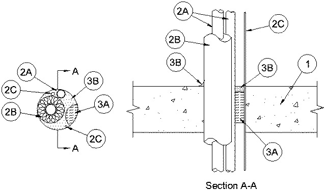
1.Floor or Wall Assembly — Min 4-1/2 in. (114 mm) thick reinforced lightweight or normal weight (100-150 pcf or 1600 - 2400 kg/m3) concrete. Floor may also be constructed of any min 6 in. (152 mm) thick UL Classified hollow-core Precast Concrete Units*. Wall may also be constructed of any UL Classified Concrete Blocks*. Max diam of opening is 4 in. (102 mm).
See Concrete Blocks (CAZT) and Precast Concrete Units (CFTV) categories in the Fire Resistance Directory for names of manufacturers.
2.Through Penetrants — Metallic pipes, tubing or cable to be installed either concentrically or eccentrically within the firestop system. Penetrants to be rigidly supported on both sides of floor assembly. The following types and sizes of penetrants may be used:
A.Metallic Pipes — Max two metallic pipes or tubing. The annular space between penetrant and periphery of opening shall be min 0 in. (point contact) to max 2-1/4 in. (57 mm). The following types and sizes of metallic pipes or tubing may be used:
A1.Copper Tubing — Nom 1 in. (25 mm) diam (or smaller) Type M (or heavier) copper tube.A2.Copper Pipe — Nom 1 in. (25 mm) diam (or smaller) Regular (or heavier) copper pipe.A3.Steel Pipe — Nom 1 in. (25 mm) diam (or smaller) Schedule 10 steel pipe.B.Tube Insulation - Plastics+ — Nom 3/4 in. (19 mm) thick acrylonitrile butadiene/polyvinyl chloride (AB/PVC) flexible foam furnished in the form of tubing. The tube insulation may be installed on all tubing. The annular space between the insulated penetrating item and uninsulated metallic pipes, conduit or tubing shall be min 0 in. ( point contact) to max 1-1/4 in. (32 mm) The annular space between the insulated penetrating item and the periphery of the opening shall be min 0 in. ( point contact) to max 2-1/4 in. (57 mm).See Plastics (QMFZ2) category in the Recognized Component Directory for names of manufacturers. Any Recognized Component tube insulation material meeting the above specifications and having a UL 94 Flammability Classification of 94-5A may be used.
C.Cables — Max two cables spaced min 0 in. ( point contact) from tube insulation or min 1/2 in. (13 mm) from other penetrants. The annular space between cable and periphery of opening is min 0 in. ( point contact) to max 2-1/4 in. (57 mm). Cables to be rigidly supported on both sides of floor or wall assembly. The following types and sizes of cables may be used:
C1.Max 7/C No. 24 AWG (or smaller) control cable with polyvinyl chloride (PVC) insulation and jacket. C2.Max 2/C No. 10 AWG (or smaller) thermostat wire.
3.Firestop System — The firestop system shall consist of the following:
A.Packing Material — Min 3 in. (76 mm) thickness of min 4 pcf (64 kg/m3) mineral wool batt insulation firmly packed into opening as a permanent form. Packing material to be recessed from top surface of floor or both surfaces of wall to accommodate the required thickness of fill material. When the floor is constructed of hollow-core precast concrete units, packing material shall be recessed from both surfaces of floor to accommodate the required thickness of fill material.B.Fill, Void or Cavity Materials* - Sealant — Min 1/2 in. (13 mm) thickness of fill material applied within the annulus, flush with top surface of floor or both surfaces of wall. Min 1/2 in. (13 mm) diam bead of fill material applied to the penetrant/concrete interface at the point contact location on the top surface of floor or both surfaces of wall. When the floor is constructed of hollow-core precast concrete units, fill material shall be installed flush with both surfaces of floor. If FS 900+ Sealant is used, sealant shall be forced into interstices between penetrants to max extent possible.
RECTORSEAL — FlameSafe FS 1900, FlameSafe FS 900+, Metacaulk MC 150+, Metacaulk 1000, Metacaulk 350i, Biostop BF 150+, Biostop 350i or Biostop 500+
+Bearing the UL Recognized Component Marking