C-AJ-8159
June 3, 2011
June 3, 2011
F Rating — 2 Hr
T Rating — 1/2 Hr
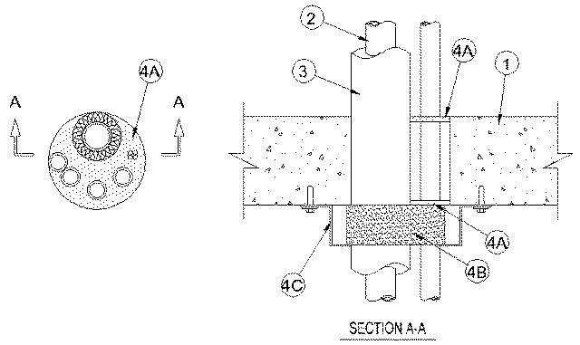
1.Floor or Wall Assembly — Min 2-1/2 in. (64 mm) thick reinforced lightweight or normal weight (100-150 pcf or 1600-2400 kg/m3) concrete. Wall may also be constructed of any UL Classified Concrete Blocks*. Max diam of opening 5 in. (127 mm)
See Concrete Blocks (CAZT) category in Fire Resistance Directory for names of manufacturers.
2.Through Penetrants — A max of five pipes, conduits or tubes and a max of three cable lengths to be installed within the opening. Annular space between the penetrants and the periphery of the opening shall be min 0 in. (point contact) to max 1/2 in. (13 mm). Penetrants to be rigidly supported on both sides of floor or wall assembly. The following types and sizes of metallic pipes, conduits or tubing may be used:
A.Metallic Pipes — A max of four metallic pipes, conduits or tubing may be used. The following types and sizes may be used:
A1.Steel Pipe — Nom 1 in. (25 mm) diam (or smaller) Schedule 5 (or heavier) steel pipe.A2.Conduit — Nom 1 in. (25 mm) diam (or smaller) electrical metallic tubing or rigid steel conduit.A3.Copper Tubing — Nom 1 in. (25 mm) diam (or smaller) Type L (or heavier) copper tubing.A4.Copper Pipe — Nom 1 in. (25 mm) diam (or smaller) Regular (or heavier) copper pipe.B.Nonmetallic Pipes — A max of one nonmetallic pipe or conduit may be used. A min 1/4 in. (6 mm) space must be maintained between uninsulated metallic pipes, conduits or tubing and nonmetallic pipes or conduits. The following types and sizes of nonmetallic pipes or conduits may be used:
B1.Polyvinyl Chloride (PVC) Pipe — Nom 1-1/2 in. (38 mm) diam (or smaller) Schedule 40 solid or cellular core PVC pipe for use in closed (process or supply) or vented (drain, waste or vent) piping system.B2.Chlorinated Polyvinyl Chloride (CPVC) Pipe — Nom 1-1/2 in. (38 mm) diam (or smaller) SDR 13.5 or Schedule 40 CPVC pipe for use in closed (process or supply) piping systems. Schedule 40 CPVC pipe for use in vented (drain, waste or vent) piping systems.B3.Rigid Nonmetallic Conduit++ — Nom 1-1/2 in. (38 mm) diam (or smaller) Schedule 40 PVC conduit installed in accordance with the National Electrical Code (NFPA No. 70.)C.Cables — A max of three cables may be used. Two lengths of max 1/C No. 12 AWG power and control cables; XLPE or PVC insulation with XLPE or PVC jacket. One length of max 9/C No. 18 AWG with PVC insulation and jacket.
3.Tube Insulation - Plastics++ — Nom 1/2 in. (13 mm) thick acrylonitrile butadiene/polyvinyl chloride (AB/PVC) flexible foam furnished in the form of tubing.
See Plastics (QMFZ2) category in the Plastics Recognized Component Directory for names of manufacturers. Any Recognized Component tube insulation material meeting the above specifications and having a UL94 Flammability Classification of 94-5VA may be used.
4.Firestop System — The firestop system shall consist of the following:
A.Fill, Void or Cavity Materials* - Caulk — Min 1/4 in. (6 mm) thickness of caulk applied within the annulus, flush with both surfaces of floor or wall.
RECTORSEAL — Metacaulk 1000, Metacaulk 150+B.Fill, Void or Cavity Material* — Wrap Strip — Nom 1/4 in. (6 mm) thick by 2 in. (51 mm) wide intumescent wrap strip. One layer of wrap strip wrapped around the bundled through-penetrants with ends butted and held in place with masking tape. Wrap strip butted tightly against bottom surface of floor or both surfaces of wall.
RECTORSEAL — Metacaulk Wrap StripC.Steel Collar — Collar fabricated from coils of precut min 0.016 in. (0.41 mm) thick (No. 28 gauge) galv steel available from fill material manufacturer. Collar shall be nom 2 in. (51 mm) deep with 1 in. (25 mm) wide by 1-1/2 in. (38 mm) long anchor tabs on 4 in. (102 mm) centers for securement to bottom surface of floor or both surfaces of wall by means of 1/4 in. (6 mm) diam by 1-1/4 in. (32 mm) long steel expansion bolts in conjunction with min 3/4 in. (19 mm) diam washers. In addition, collar contains retainer tabs 1/2 in. (13 mm) wide by 3/4 in. (19 mm) long, located opposite the anchor tabs. Collar shall be wrapped over the wrap strip, overlapping min 1 in. (25 mm)The retainer tabs are folded 90 deg towards the pipe to maintain the annular space around the pipe and to retain the wrap strip.
++ Bearing the UL Recognized Component Mark