January 15, 1999
F Rating — 3 Hr.
T Ratings — 0 and 2 Hr.
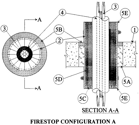

1.Floor or Wall Assembly — Min 4-1/2 in. thick reinforced lightweight or normal weight (100-150 pcf) concrete floor or min 5-1/4 in. thick reinforced lightweight or normal weight concrete wall. Wall may also be constructed of any UL Classified Concrete Blocks*. Max diam of opening is 8 in.See Concrete Blocks (CAZT) category in the Fire Resistance Directory for names of manufacturers.
2.Metallic Sleeve — Nom 6 in. diam (or smaller) Schedule 10 (or heavier) steel pipe. In floors, sleeve installed with nom 4 in. projecting below and above floor. In walls, sleeve installed to project min 4 in. beyond each surface of the wall. One sleeve to be centered within the firestop system. A nom annular space of 3/4 in. is required between the metallic tube and the periphery of the opening. Sleeve to be rigidly supported on both sides of floor or wall assembly. The T Rating of the system is dependent on the firestop configuration as shown below. Reference the descriptions of the configurations for additional details.
Firestop Configuration A — T Rating- 2 Hr
3.Through Penetrants — Beverage line consisting of max nine 3/8 in. diameter polyethylene tubes and/or max two 3/8 in. diameter Type L copper tubes tightly bundled together and centered within the metallic sleeve. Beverage line to be rigidly supported on both sides of floor or wall assembly.
4.Tube Insulation — Plastics+ — Nom 3/4 in. thick acrylonitrile butadiene/polyvinyl chloride (AB/PVC) flexible foam furnished in the form of tubing installed around through penetrants (Item 3). A nom annular space of 1-5/16 in. is required between the tube insulation and the metallic sleeve (Item 2).See Plastics+ (QMFZ2) category in the Recognized Component Directory for names of manufacturers. Any Recognized Component tube for insulation material meeting the above specifications and having a UL 94 Flammability Classification of 94-5VA may be used.
5.Firestop System — The firestop system shall consist of the following:
A.Packing Material — Min 3-3/4 in. thickness of min 4.0 pcf mineral wool batt insulation firmly packed into opening outside of metallic sleeve (Item 2) as a permanent form. Packing material to be recessed from top surface of floor or from both surfaces of wall as required to accommodate the required thickness of fill material.B.Fill, Void or Cavity Material* — Sealant — Min 3/4 in. thickness of fill material applied within the annulus, outside of metallic sleeve (Item 2), flush with top surface of floor or with both surfaces of wall.
RECTORSEAL — Metacaulk 835+C.Packing Material — Foam backer rod firmly packed into metallic sleeve as a permanent form. Packing material to be recessed within sleeve 4 in. below bottom of floor.D.Fill, Void or Cavity Material* — Sealant — Min 12 in. thickness of fil, material applied within the sleeve on top surface of packing material.
RECTORSEAL — Metacaulk 1000E.Steel Collar — Collar fabricated from colis of precut min. 0.016 in. thick (No. 28 gauge) galv steel available from the fill material manufacturer. Collar shall be nom 2 in. deep with 1 in. wide by 1-1/4 in. long anchor tabs on 4 in. centers. In addition, the collar contains retainer tabs, 3/4 in. wide, located opposite the anchor tabs. The collar shall be wrapped around the sleeve and overlapped min 5-3/4 in. The retaining tabs are folded 90 degrees towards the tube insulation (Item 4) to retain the sealant (Item 5D). Collar secured to sleeve with one 1/2 in. wide stainless steel hose clamp located at center of collar. Collars are installed on both sides of sleeve.
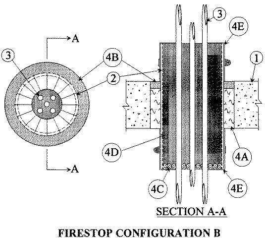
Firestop Configuration B — T Rating 0 Hr.
3.Through Penetrants — A max of nine 3/8 in. diameter polyethylene tubes and/or max of two 3/8 in. diameter Type L copper tubes installed within the opening. The space between tubes shall be min 1/2 in. The space between tubes and periphery of opening shall be min 1/2 in. Tubes to be rigidly supported on both sides of floor or wall assembly.
4.Firestop System — The firestop system shall consist of the following:
A.Packing material — Min 3-3/4 in. thickness of min 4.0 pcf mineral wool batt insulation firmly packed into opening outside of metallic sleeve (Item 2) as a permanent form. Packing material to be recessed from top surface of floor or from both surfaces of wall as required to accommodate the required thickness of fill material.B.Fill, Void or Cavity Material* — Sealant — Min 3/4 in. thickness of fill material applied within the annulus, outside of metallic sleeve (Item 2), flush with top surface of floor or with both surfaces of wall.
RECTORSEAL — Metacaulk 835+C.Packing Material — Foam backer rod firmly packed into metallic sleeve as a permanent form. Packing material to be recessed within sleeve 4 in. below bottom of floor.D.Fill, Void or Cavity Material* — Sealant — Min 12 in. thickness of fill material applied within the sleeve, on top surface of packing material.
RECTORSEAL — Metacaulk 1000E.Steel Collar — Collar fabricated from coils of precut min 0.016 in. thick (No 28 gauge) galv steel available from the fill material manufacturer. Collar shall be nom 2 in. deep with 1 in. wide by 1-1/4 in. long anchor tabs on 4 in. centers for securement. In addition, the collar contains retainer tabs, 3/4 in. wide, located opposite the anchor tabs. The collar shall be wrapped around the sleeve and overlapped min 5-3/4 in. The retaining tabs are folded 90 degrees towards the through penetrants (Item 3) to retain the sealant (Item 4D). Collar secured to sleeve with one 1/2 in. wide stainless steel hose clamp located at center of collar. Collars are installed on both sides of sleeve.
Firestop Configuration C — T Rating 2 Hr.
3.Through Penetrants — Beverage line consisting of max nine 3/8 in. diameter polyethylene tubes and/or max two 3/8 in. diameter Type L copper tubes tightly bundled together and centered within the metallic sleeve. Beverage line to be rigidly supported on both sides of floor or wall assembly.
4.Tube Insulation — Plastics+ — Nom 3/4 in. thick acrylonitrile butadiene/polyvinyl chloride (AB/PVC) flexible foam furnished in the form of tubing installed around through penetrants (Item 3). A nom annular space of 1-5/16 in. is required between the tube insulation and the metallic sleeve (Item 2).See Plastics+ — (QMFZ2) category in the Recognized Component Directory for names of manufacturers. Any Recognized Component tube insulation material meeting the above specifications and having a UL 94 Flammability Classification of 94-5VA may be used.
5.Firestop System — The firestop system shall consist of the following:
A.Packing Material — Min 3-3/4 in. thickness of min 4.0 pcf mineral wool batt insulation firmly packed into opening outside of metallic sleeve (Item 2) as a permanent form. Packing material to be recessed from top surface of floor or from both surfaces of wall as required to accommodate the required thickness of fill material.B.Fill, Void or Cavity Material* — Sealant — Min 3/4 in thickness of fill material applied within the annulus, outside of metallic sleeve (Item 2), flush with top surface of floor or with both surfaces of wall.
RECTORSEAL — Metacaulk 835+C.Packing Material — Min 4 in. thickness of min 4.0 pcf mineral wool batt insulation firmly packed into sleeve as a permanent form. Packing material to be installed within sleeve flush with top surface of floor or both surfaces of wall.D.Fill, Void or Cavity Material* — Sealant — Min 4 in. thickness of fill material applied within the sleeve, on top surface of packing material. In walls, fill material applied within the sleeve over both surfaces of packing material.
RECTORSEAL — Metacaulk 1000E.Steel Collar — Collar fabricated from coils of precut min 0.016 in. thick (No. 28 gauge) galv steel available from the fill material manufacturer. Collar shall be nom 2 in. deep with 1 in. wide by 1-1/4 in. long anchor tabs on 4 in. centers. In addition, the collar contains retainer tabs, 3/4in. wide, located opposite the anchor tabs. The collar shall be wrapped around the sleeve and overlapped min 5-3/4 in. The retaining tabs are folded 90 degrees towards the tube insulation (Item 4) to retain the sealant (Item 5D). Collar secured to sleeve with one 1/2 in. wide stainless steel hose clamp located at center of collar. Collars are installed on top surface of sleeves installed in floors or both ends of sleeve installed in walls.
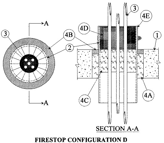
Firestop Configuration D — T Rating 0 Hr.
3.Through Penetrants — A max of nine 3/8 in. diameter polyethylene tubes and/or max of two 3/8 in. diameter Type L copper tubes installed within the opening. The space between tubes shall be min 1/2 in. THe space between tubes and periphery of opening shall be min 1/2 in. Tubes to be rigidly supported on both sides of floor or wall assembly.
4.Firestop System — The firestop system shall consist of the following:
A.Packing Material — Min 3-3/4 in. thickness of min 4.0 pcf mineral wool batt insulation firmly packed into opening outside of metallic sleeve (Item 2) as a permanent form. Packing material to be recessed from top surface of floor required thickness of fill material.B.Fill, Void or Cavity Material* — Sealant — Min 3/4 in. thickness of fill material applied within the annulus, outside of metallic sleeve (Item 2), flush with top surface of floor or with both surfaces of wall.
RECTORSEAL — Metacaulk 835+C.Packing Material — Min 4 in. thickness of fill min 4.0 pcf mineral wool batt insulation firmly packed into sleeve as a permanent form. Packing material to be installed within sleeve flush with top surface of floor or both surfaces of wall.D.Fill, Void or Cavity Material* — Sealant — Min 4 in. thickness of fill material applied within the sleeve, on top surface of packing material. In walls, fill material applied within the sleeve over both surfaces of packing material.
RECTORSEAL — Metacaulk 1000E.Steel Collar — Collar fabricated from coils of precut min 0.016 in. thick (No. 28 gauge) galv steel available from the fill material manufacturer. Collar shall be nom 2 in. deep with 1 in. wide by 1-1/4 in. long anchor tabs on 4 in. centers. In addition, the collar contains retainer tabs, 3/4 in. wide, located opposite the anchor tabs. The collar shall be wrapped around the sleeve and overlapped min 5-3/4 in. The retaining tabs are folded 90 degrees towards the through penetrants (Item 3) to retain the sealant (Item 4D). Collar secured to sleeve with one 1/2 in. wide stainless steel hose clamp located at center of collar. Collars are installed on top surface of sleeves installed in floors or both ends of sleeve installed in walls.