C-AJ-8043
February 5, 2018
February 5, 2018
| ANSI/UL1479 (ASTM E814) | CAN/ULC S115 |
|---|---|
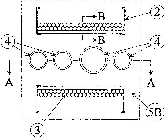
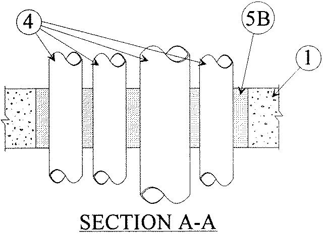
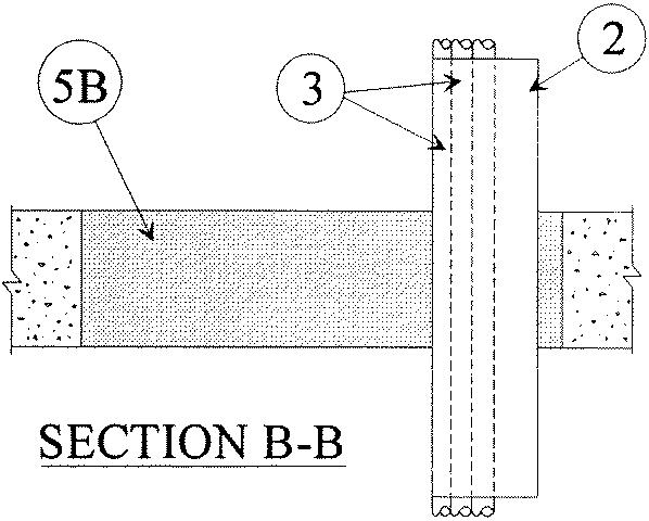
1.Floor or Wall Assembly — Min 2-1/2 in. (64 mm) or 4-1/2 in. (114 mm) thick reinforced lightweight or normal weight (100-150 pcf or 1600-2400 kg/m3) concrete. The hourly F and FH Ratings are 2 and 4 hr for min 2-1/2 in. (64 mm) and min 4-1/2 in. (114 mm) thick concrete, respectively. Wall may also be constructed of any UL Classified Concrete Blocks*. Max area of opening is 1024 sq in. (6606 cm2) with max dimension of 32 in. (813 mm).See Concrete Blocks (CAZT) category in the Fire Resistance Directory for names of manufacturers.
2.Cable Tray+ — A max of two cable trays may be installed within the opening. Annular space between cable tray and periphery of opening shall be min of 2 in. (51 mm). Cable trays shall be spaced a min of 5 in. (127 mm) apart and rigidly supported on both sides of the floor or wall assembly. The following types of cable trays may be used:
A.Max 24 in. (610 mm) wide by max 6 in. (152 mm) deep open ladder cable tray with channel-shaped side rails formed of min 0.050 in. (1.27 mm) thick (No. 18 MSG) galv steel and with 7/8 in. (22 mm) wide by 7/8 in. (22 mm) deep rungs spaced 9 in. (229 mm) OC. B.Max 24 in. (152 mm) wide by max 6 in. (152 mm) deep open ladder cable tray with channel-shaped side rails formed of min 0.073 in. (1.85 mm) thick aluminum and with 1 in. (25 mm) wide by 1 in. (25 mm) deep rungs spaced 9 in. (229 mm) OC.
3.Cables — Aggregate cross-sectional area of cables in cable tray to be max 27 percent of the cross-sectional area of the cable tray based on the full loading depth within the cable tray. Any combination of the following types and sizes of copper conductor cables may be used:
A.Max 1/C 500 kcmil power cable with nylon jacket. B.Max 1/C 300 kcmil power cable with nylon jacket. C.Max 25 pair No. 24 AWG (or smaller) polyvinyl chloride (PVC) insulated and jacketed telephone cables. D.Max 3/C W/Ground No. 12 AWG cable with PVC insulation and jacket. E.Multiple 2 lead fiber optical communication cable jacketed with PVC and having a max outside dimension of 0.12 x 0.24 in. (3 x 6.1 mm).
4.Through-Penetrants — A max of 4 pipes, conduits or tubing to be installed within the opening. The space between pipes, conduits or tubing shall be min 2-1/2 in. (64 mm). The space between pipes, conduits or tubing and periphery of opening shall be min 2-1/2 in. (64 mm). The space between pipes, conduits or tubing and cable trays shall be min 5 in. (127 mm). Pipe, conduit or tubing to be rigidly supported on both sides of floor or wall assembly. The following types and sizes of metallic pipes, conduits or tubing may be used:
A.Steel Pipe — Nom 6 in. (152 mm) diam (or smaller) Schedule 10 (or heavier) steel pipe.B.Iron Pipe — Nom 6 in. (152 mm) diam (or smaller) cast or ductile iron pipe.C.Conduit — Nom 4 in. (102 mm) diam (or smaller) steel electrical metallic tubing.D.Conduit — Nom 6 in. (152 mm) diam (or smaller) rigid steel conduit.E.Copper Tubing — Nom 6 in. (152 mm) diam (or smaller) Type L (or heavier) copper tubing.F.Copper Pipe — Nom 6 in. (152 mm) diam (or smaller) Regular (or heavier) copper pipe.
5.Firestop System — The firestop system shall consist of the following:
A.Forms — (Not Shown) — Used as a form to prevent leakage of fill material during installation. Forms to be a rigid sheet material, cut to fit the contour of the penetrating items and located where necessary for installation of fill material. Forms to be removed after fill material has cured.B.Fill, Void or Cavity Material* — Mortar — Min 2-1/2 in. (64 mm) or min 4-1/2 in. (114 mm) thickness of fill material for 2 and 4 hr rated assemblies, respectively, applied within the annulus. Mortar to be forced into interstices of cables to max extent possible. Mortar is mixed at a rate of 2-1/2 parts dry mix to one part water by volume in accordance with the fill material manufacturer's installation instructions.
RECTORSEAL — Metalcaulk Fire Rated Mortar