C-AJ-7199
November 9, 2020
November 9, 2020
| ANSI/UL1479 (ASTM E814) | CAN/ULC S115 |
|---|---|

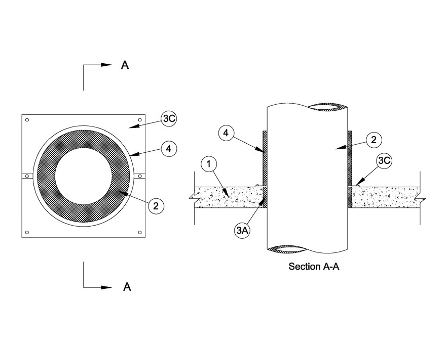
1.Floor or Wall Assembly — Min 4-1/2 in. (114 mm) thick reinforced lightweight or normal weight (100-150 pcf or 1600-2400 kg/m3) concrete. Wall may also be constructed of any UL Classified Concrete Blocks*. Max area of opening is 13.75 ft2 (1.28 m2) with max dimensions of 44-1/2 in. (1.13 m).
See Concrete Blocks (CAZT) category in the Fire Resistance Directory for names of manufacturers.
2.Through Penetrating Product* — One of the following types of Through-Penetrating Products* may be installed within the opening:
A.Grease Duct* — Nom 36 in. (914 mm) inside diam (or smaller) UL Listed grease duct. One grease duct to be installed concentrically or eccentrically within the firestop system. The annular space between grease duct and periphery of opening shall be min 1/2 in. (13 mm) to max 1-1/2 in. (38 mm). Grease duct to be rigidly supported on both sides of floor or wall assembly.
JEREMIAS INC —DWFL-ZC and DWCK-ZC
B.Ventilation Duct* — Nom 36 in. (914 mm) inside diam (or smaller) factory fabricated UL Listed special gas vent. One ventilation duct to be installed concentrically or eccentrically within the firestop system. The annular space between ventilation duct and periphery of opening shall be min 1/2 in. (13 mm) to max 1-1/2 in. (38 mm). Ventilation duct to be rigidly supported on both sides of floor or wall assembly.
JEREMIAS INC —DWGV-ZC and DWCK-ZC
3.Firestop System — The firestop system shall consist of the following:
A.Packing Material — Min 4-1/2 in. (114 mm) thickness of min 10 pcf (160 kg/m3) ceramic fiber insulation firmly packed into opening as a permanent form. Packing material to be installed flush with both surfaces of the floor or wall.B.Fill, Void or Cavity Material* — (Not Shown) Prior to the installation of the steel cover plate, min 1/4 in. (6 mm) bead of fill material applied as a gasket between the concrete and the steel cover plate on the top surface of the floor and both surfaces of the wall. Additional min 1/4 in. (6 mm) bead of fill material applied at the interface of the steel plate and the grease duct on both sides of the floor and wall.
HILTI CONSTRUCTION CHEMICALS, DIV OF HILTI INC —FS-ONE Sealant
SPECIFIED TECHNOLOGIES INC —SpecSeal Series SSS
3M COMPANY 3M FIRE PROTECTION PRODUCTS —IC CP-25 WB+
RECTORSEAL —Metacaulk 1000 Caulk C.Cover Plate — Min 0.035 in. (0.89 mm) thick galv steel cover plate cut to follow the contour of the grease duct (Item 2), applied to both surfaces of floor and wall. Two piece cover plate installed with min 2 in. (51 mm) overlapping seams and a min 2 in. (51 mm) overlap onto the concrete. Cover plate secured to concrete using 1/4 in. (6 mm) diam by 1-1/4 in. (32 mm) long steel concrete screws, spaced a max 12 in. (305 mm) OC.
4.Closure Band — Min 0.025 in. (0.63 mm) thick steel, 12 in. (305 mm) wide, lined on the interior with 1 in. thick 10 pcf (160 kg/m3) ceramic fiber blanket supplied by the grease or ventilation duct manufacturer. Two piece closure band installed around grease or ventilation duct (Item 2) in contact with cover plate and secured together with 1/4-20 by 1-1/2 in. (38 mm) long steel bolts and nuts. Closure bands installed on top surface of floor and on both surfaces of wall.