C-AJ-7088
April 16, 2019
April 16, 2019
| ANSI/UL1479 (ASTM E814) | CAN/ULC S115 |
|---|---|
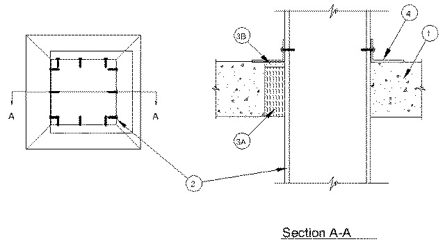
1.Floor or Wall Assembly — Min 4-1/2 in. (114 mm) thick reinforced lightweight or normal weight (100-150 pcf or 1600-2400 kg/m3) concrete. Wall may also be constructed of any UL Classified Concrete Blocks*. Max area of opening is 7.1 sq ft (0.66 m2) with max dimension of 32 in. (813 mm).
See Concrete Blocks (CAZT) category in the Fire Resistance Directory for names of manufacturers.
2.Steel Duct — Max 30 by 30 in. (762 by 762 mm) by No. 24 gauge (or heavier) galv steel duct. One steel duct to be positioned within the firestop system. The annular space shall be min 0 in. (point contact) to max 2 in. (51 mm). When W Rating applies, the annular space shall be min 1/2 in. (13 mm). Duct to be rigidly supported on both sides of floor or wall assembly.
3.Firestop System — The firestop system shall consist of the following:
A.Packing Material — Min 4 in. (102 mm) thickness of min pcf (64 kg/m3) mineral wool batt insulation firmly packed into opening as a permanent form. Packing material to be recessed from top surface of floor or from both surfaces of wall as required to accommodate the required thickness of fill material.B.Fill, Void or Cavity Material* — Spray or Caulk — Min 1/8 in. (3 mm) wet thickness (min 1/16 in. or 1.6 mm dry thickness) of fill material applied within the annulus, flush with top surface of floor or with both surfaces of wall. When W Rating applies, spray shall be applied with a min 3/8 in. dry thickness.
RECTORSEAL —Metacaulk 1200 Spray, Metacaulk 1200 Caulk Grade, Metacaulk 1200 SL (floors only), Metacaulk MC 150+ or Metacaulk 1000. W Rating applies only when Metacaulk MC 150+ or Metacaulk 1000 is used.
4.Steel Retaining Angle — Nom 2 by 4 in. (51 by 102 mm) by No. 22 gauge (or heavier) steel angles attached to steel duct on all four sides on the top surface of floor or both surfaces of wall. The angles shall be attached to the duct with No. 8 (or larger) steel sheet metal screws spaced max of 2 in. (51 mm) OC along any edge having an annular space of 0 in. (0 mm, point contact), and 4-1/2 in. (114 mm) OC elsewhere.