C-AJ-4038
January 6, 2010
January 6, 2010
F Rating — 3 Hr
T Rating — 0 Hr
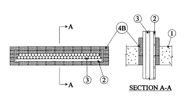
1.Floor or Wall Assembly — Min 4-1/2 in. thick reinforced normal weight (100-150 pcf) concrete. Wall may also be constructed of any UL Classified Concrete Blocks*. Max area of opening is 280 sq in. with max dimension of 40 in.See Concrete Blocks (CAZT) category in the Fire Resistance Directory for names of manufacturers.
2.Cable Tray* — Max 36 in. wide by max 5 in. deep open-ladder cable tray with channel-shaped side rails formed of 0.090 in. thick aluminum and with 1 in. wide by 1 in. deep rungs spaced 9 in. OC. Max one cable tray to be centered in the opening. The annular space between the rungs of the cable tray and the periphery of the opening shall be a nom 2 in. The annular space between the side rails of the cable tray and the periphery of the opening shall be a nom 1in. Cable tray to be rigidly supported on both sides of floor or wall assembly.
3.Cables — Aggregate cross-sectional area of cables in cable trays to be max 20 percent of the cross-sectional area of the cable tray based on a max 4 in. cable loading depth within the cable tray. Any combination of the following types and sizes of copper conductor cables may be used:
A.Max 1/C - kcmil (or smaller0 cable with polyvinyl chloride (PVC) insulation and jacket or hypalon insulation and ethylene propylene rubber jacket. B.Max 16/C - No. 16 AWG (or smaller) cable with PVC insulation and jacket. C.Max 4/C - No. 12 AWG (or smaller) cable with rubber insulation and neoprene jacket. D.Max 100 pair No. 24 AWG (or smaller) cable with PVC insulation and jacket.
4.Firestop System — The firestop system shall consist of the following:
A.Forms — (Not Shown) — Used to keep the fill material (Item 4B) in place during the installation. Forms to plywood sheets, cut to fit the contour of the penetrating items. In floors, fastened to the underside of the floor. In walls, forms fastened to one side of wall and positioned to accommodate the required thickness of fill material. Forms shall be removed after the installation of the fill material.B.Fill, Void or Cavity Materials* — Pillows — Max 13-1/2 in. long by 7 in. wide by 1-1/2 in. thick pillow-like material. Prior to installation of fill material, fill material shall be patted down by hand and folded in half lengthwise. In floors, pillows shall be installed vertically (on edge) within the opening in such a manner that the ends are flush with the bottom surface of the floor and project a min of 2-1/2 in. beyond the top surface of floor. In walls, pillows shall be installed horizontally (on edge) within the opening in such a manner that the ends project a min of 2-1/2 in. beyond both surfaces of wall. Pillows shall be tightly packed and forced into opening to fill the annular space between cables and periphery of opening and between cable tray and periphery of opening. During installation of fill material, fill material shall be weaved between or wrapped around any loose individual cables or between loose cable bundles to seal any voids between cables and cable bundles.
RECTORSEAL — FlameSafe® BagsC.Wire Lath — (Not Shown) — Optional, after the removal of the plywood sheet and installation of the fill material, nom 1 in. diamond shaped wire lath fabricated from min No. 19 AWG galv steel wire may be installed on both surfaces of the floor or wall. Wire lath cut to fit the contour of the penetrating items with a min 2 in. lap beyond the periphery of the opening. Wire lath secured to both surfaces of floor or wall assembly with 1/4 in. diam by 1-3/4 in. long concrete anchors in conjunction with 1/4 in. by 1-1/4 in. diam steel fender washers, spaced 4 in. OC.