C-AJ-3304
September 7, 2010
September 7, 2010
F Rating — 3 Hr
T Rating — 1 Hr
L Rating At Ambient — 2.5 CFM/Device
L Rating At 400 F — Less than 1 CFM/Device
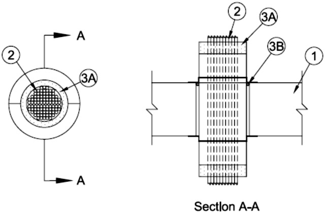
1.Floor or Wall Assembly — Min 4-1/2 in. (114 mm) thick reinforced lightweight or normal weight (100-150 pcf or 1600-2400 kg/m3) concrete. Wall may also be constructed of any UL Classified Concrete Blocks*. Diam of opening to be 2 in. or 4 in. (51 or 102 mm) to accommodate firestop device (Item 3A).
See Concrete Blocks (CAZT) category in Fire Resistance Directory for names of manufacturers.
2.Cables — Aggregate cross-sectional area of cables in firestop device (Item 3A) to be max 70 percent of the aggregate cross-sectional area of the firestop device. One or more cables may be installed concentrically within the firestop device. Any combination of the following types and sizes of cables may be used:
A.Max 2/C No. 18 AWG with polyvinyl chloride (PVC) insulation and jacket materials. B.Max 4 pair No. 24 AWG telephone cable with PVC insulation and jacket materials. C.Max RG/U (or smaller) coaxial cable with fluorinated ethylene insulation and jacket materials. D.Max 3/C (with ground) No. 14 AWG (or smaller) nonmetallic sheathed (Romex) cable with PVC insulation and jacket materials. E.Max /C No. 4 AWG copper conductor cable with insulation and jacket materials. F.Max 12 core No. 26 AWG shielded multi coax cable with foam high density polyethylene insulation and PVC jacket. G.1/C No. 8 AWG copper conductor cable with PVC insulation and nylon jacket materials. H.Max 100 pair No. 24 AWG copper conductor telephone cable with PVC insulation and jacket materials. I.Max 7/C No. 12 AWG copper conductors with PVC insulation and jacket materials. J.Max 62.5/125 micron fiber optic cables with having a min Riser rating.
3.Firestop System — The firestop system shall consist of the following:
A.Firestop Device* — Nom 2 in or 4 in. (51 or 102 mm) diam by 10 in. (254 mm) powdered coated steel transit incorporating internal intumescent material, foam plugs and mounting flanges. Firestop device to be friction fit within opening and installed with its ends projecting an equal distance beyond each surface of the floor or wall assembly in accordance with the accompanying installation instructions. The annular space between the firestop device and the periphery of the opening shall be nom 1/16 in. (1.6 mm). Firestop device secured in place by means of fill material (Item 3B) and steel split mounting flanges sized to accommodate the firestop device. Steel split mounting flanges installed on both sides of floor or wall after installation of fill material and secured together with supplied steel set screws. Nom 1 in. (25 mm) thick foam plugs installed flush with each end of device on both sides of floor or wall assembly.
RECTORSEAL — Metacaulk® 2" round Pass Through Device Metacaulk® 4" round Pass Through DeviceB.Fill, Void or Cavity Materials* - Sealant — Min 1/8 in. (3 mm) thickness of fill material applied within the annulus, flush with top surface of floor or with both surfaces of wall prior to the installation of the mounting flanges.
RECTORSEAL — Metacaulk 1000 or Fireputty pad.