June 26, 2023
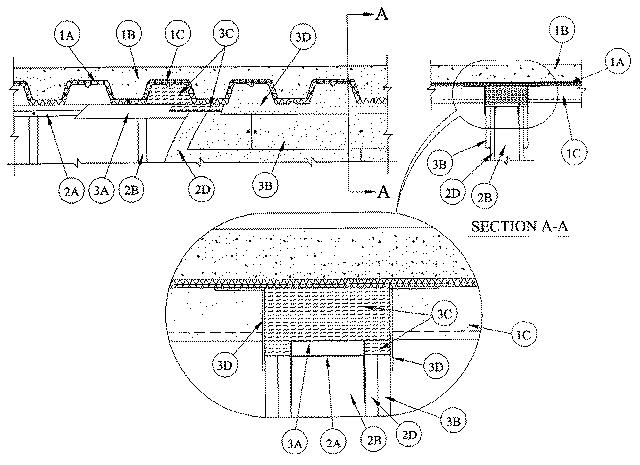
1.Floor Assembly — The fire-rated fluted steel deck/concrete floor assembly shall be constructed of the materials and in the manner described in the individual D700 Series Floor-Ceiling Design in the UL Fire Resistance Directory. The hourly fire rating of the floor assembly shall be equal to or greater than the hourly fire rating of the wall assembly. The floor assembly shall include the following construction features:A.Steel Floor And Form Units* — Max 3 in. deep galv steel fluted floor units.B.Concrete — Min 2-1/2 in. thick reinforced concrete, as measured from the top plane of the floor units.C.Spray-Applied Fire Resistive Material* — Prior to the installation of the deflection channel, gypsum board strips, forming material and fill material (Items 3A, 3B, 3C and 3D, respectively ), steel floor units to be sprayed with a min 5/16 in. to max 1-3/4 in. thickness of material in accordance with the specifications in the individual D700 Series Design.
GCP APPLIED TECHNOLOGIES INC — MK-6/HY
2.Wall Assembly — The 1, 2 or 3 hr fire rated gypsum board/steel stud wall assembly shall be constructed of the materials and in the manner described in the individual U400 or V400 Series Wall and Partition Design in the UL Fire Resistance Directory and shall include the following construction features:A.Steel Floor And Ceiling Runners — Floor and ceiling runners of wall assembly shall consist of galv steel channels sized to accommodate steel studs (Item 2B). Ceiling runner to be provided with 1 in. flanges. When U-shaped deflection channel (Item 3A) is used, ceiling runner installed within the U-shaped deflection channel (Item 3A) with a 1 in. gap maintained between the top of ceiling runner and top of deflection channel. When deflection channel is not used, the ceiling runner shall have min. 2-3/4 in. flanges. Ceiling runner installed perpendicular to direction of fluted steel deck and secured to valleys through spray-applied fire resistive material with steel masonry anchors spaced a max 12 in. OC.A1.Light Gauge Framing*— Slotted Ceiling Runner — As an alternative to the ceiling runner in Item 2A, slotted ceiling runner to consist of galv steel channel with slotted flanges sized to accommodate steel studs (Item 2B). Slotted ceiling runner installed perpendicular to direction of fluted steel deck and secured to valleys through spray-applied fire resistive material with steel masonry anchors spaced max 24 in. OC. When slotted ceiling runner is used, deflection channel (Item 3A) shall not be used.
CEMCO, LLC — CST
BRADY CONSTRUCTION INNOVATIONS INC, DBA SLIPTRACK SYSTEMS — SLP-TRKA2.Light Gauge Framing*- Notched Ceiling Runner — As an alternate to the ceiling runners in Items 2A through 2A2, notched ceiling runners to consist of C-shaped galv steel channel with notched return flanges sized to accommodate steel studs (Item 2B). Notched ceiling runner installed perpendicular to direction of fluted steel deck and secured to valleys through spray-applied fire resistive material with steel masonry anchors spaced max 24 in. OC. When notched ceiling runner is used, deflection channel (Item 3A) shall not be used.
OLMAR SUPPLY INC — Type SCRB.Studs — Steel studs to be min 3-1/2 in. wide. Studs cut 1-1/2 in. less in length than assembly height. When deflection channel is used, studs shall be installed with bottom nesting in and resting on floor runner and with top nesting in ceiling runner. Studs secured to floor and ceiling runners with sheet metal screw. When deflection channel is not used, studs shall not be secured to ceiling runner. When slotted ceiling runner (Item 2A1) is used, steel studs, secured to slotted ceiling runner with No. 8 x 1/2 in. long wafer head steel screws at midheight of slot on each side of wall. Stud spacing not to exceed 24 in. OC.C.Batts and Blankets* — (Not Shown) —Mineral wool or fiberglass insulation batts, friction-fitted between studs and ceiling and floor runners, as required in the individual Wall and Partition Design.D.Gypsum Board* — Gypsum board sheets installed to a min total thickness of 5/8, 3/4 or 1-1/2 in. on each side of wall for 1, 2 or 3 hr rated assemblies, respectively. Wall to be constructed as specified in the individual Wall and Partition Design, except that a nom 1 in. gap shall be maintained between the top of the gypsum board and the bottom of the spray-applied fire resistive material and the top row of screws shall be installed into the studs 4 to 4-1/2 in. below the top edge of the gypsum board.The hourly assembly rating of the joint system is equal to the hourly fire rating of the wall.
3.Joint System — Max separation between bottom of spray-applied fire resistive material and top of wall at time of installation of joint system is 1 in. The joint system is designed to accommodate a max of 25 percent compression or extension from its installed width. The joint system consists of an optional deflection channel, gypsum board strips, a forming material and a fill material, as follows:A.Deflection Channel — (Optional) A nom 3-11/16 in. wide by 3 in. deep min No. 22 gauge steel U-shaped channel. Deflection channel installed perpendicular to direction of fluted steel deck and secured to valleys through spray-applied fire resistive material with steel masonry anchors spaced max 12 in. OC. The ceiling runner (Item 2A) is installed within the deflection channel to maintain a 1 in. gap between the top of the ceiling runner and the top of the deflection channel. The ceiling runner is not fastened to the deflection channel.B.Gypsum Board* — For 1 and 2 hr rated assemblies, a min 12 in. wide strip of min 1/2 in. thick gypsum board shall be installed over the full sheets of gypsum board on each side of wall when the thickness of gypsum board installed on each side of wall is less than 1-1/4 in. The top edge of the strip shall be flush with the top edge of the full sheets and shall be secured to steel studs with 1-5/8 in. long Type S steel screw spaced max 6 in. OC. Strip also secured to full sheets midway between studs with 1-5/8 in. long Type G steel laminating screws spaced max 6 in. OC vertically. Uppermost screw securing the strip shall be located 4 to 4-1/2 in. below the lower surface of the floor. Joints of strip to be offset from joints of full sheets. Joints covered with paper tape and joint compound.See Gypsum Board (CKNX) category for names of manufacturers.
C.Forming Material* — (For 1 and 2 hr ratings) Min 3-1/2 in. thickness of min 4 pcf density mineral wool batt insulation cut to the shape of the fluted steel floor units, approx 33 percent larger than the area of the flutes. Pieces compressed and inserted vertically into the flutes above the top of the defection channel or ceiling runner. The mineral wool is to be flush with each side of the deflection channel or ceiling runner. Additional min 1-1/4 in. thickness of min pcf mineral wool insulation cut larger than the contour of the flutes and the max 1 in. gap above the top of the gypsum board, compressed 33 percent and firmly packed into the flutes and the gap between the top of the gypsum board and the bottom of the steel units, flush with both surfaces of the wall.(For 3 hr rating) Min 8 pcf density mineral wool batt insulation cut approx 25 percent wider than the flutes and with a length approx equal to the overall thickness of the wall. Pieces stacked as needed and then compressed 33 percent in thickness and inserted into the flutes of the steel floor units above the top of the deflection channel. The mineral wool batt insulation is to project beyond each side of the deflection channel, flush with wall surfaces. Additional min 8 pcf mineral wool batt insulation shall be cut into strips to fill the gap between the top of the gypsum board and bottom of the protected steel floor units. The width of the strips shall be equal to the total thickness of the gypsum board. The strips of mineral wool are compressed 50 percent in thickness and firmly packed into the gap between the top of the gypsum board and bottom of the spray-applied fire resistive material, flush with wall surfaces.
ROCK WOOL MANUFACTURING CO — Delta BoardD.Fill, Void or Cavity Material* — (For 1 and 2 hr ratings) Min 1/8 in. wet thickness of fill material sprayed or troweled on each side of the wall to completely cover mineral wool forming material and to overlap a min of 1/2 in. onto gypsum board and steel deck on both sides of wall.(For 3 hr ratings) Min 1/4 in. wet thickness of fill material sprayed or troweled on each side of the wall to completely cover mineral wool forming material and to overlap a min of 1/2 in. onto gypsum board and 3 in. onto spray-applied fire resistive material on both sides of wall.
RECTORSEAL — Metacaulk 1200 Spray, Metacaulk 1200 Caulk Grade