
June 25, 2021
June 25, 2021
|
ANSI / UL2079 |
CAN / ULC S115 |
|
Assembly Rating — 2 Hr |
F Rating — 2 Hr |
|
Nominal Joint Width – 1-3/4 In. |
FT Rating — 2 Hr |
|
Class II Movement Capabilities — 13.3% Extension or 8% Compression |
FH Rating — 2 Hr |
|
L Rating At Ambient — Less Than 1 CFM/Lin Ft |
FTH Rating — 2 Hr |
|
L Rating At 400°F — Less Than 1 CFM/Lin Ft |
Nominal Joint Width – 45 mm |
|
|
Class II Movement Capabilities --13.3% Extension or 8% Compression |
|
|
L Rating At Ambient — Less Than 1.55 L/s/m |
|
|
L Rating At 400°F — Less Than 1.55 L/s/m |
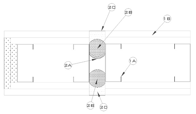

Config A
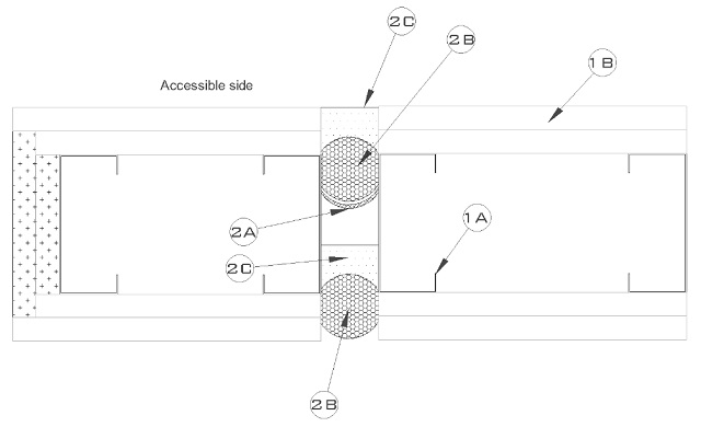
Config B
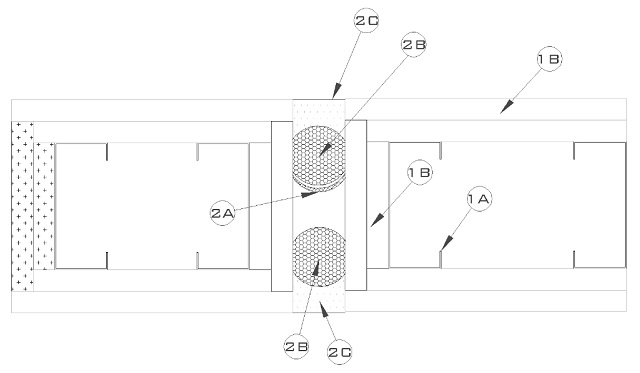
Config C
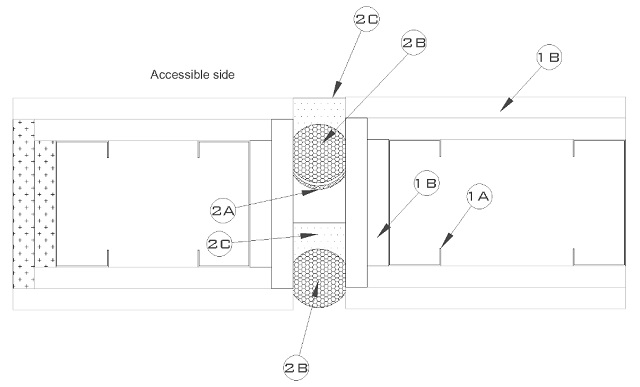
Config D
1. Wall Assembly — The 2 hr fire rated framed gypsum board wall assembly shall be constructed of the materials and in the manner described in the individual U300, U400 or V400 Series Wall and Partition Design in the UL Fire Resistance Directory and shall include the following construction features:
A. Studs — Wall framing may consist of either wood studs or steel channel studs. Wood studs to consist of min 2 by 4 in. (51 by 102 mm) lumber spaced 16 in. (406 mm) O.C. Steel studs to be min 3-5/8 in. (92 mm) wide and spaced max 24 in. (610 mm) O.C.
B. Gypsum Board* — Gypsum board sheets to be installed to a min total thickness of 1-1/4 in. (32 mm) on each side of the wall. As an option additional gypsum board sheets installed to a min total thickness of 5/8 in. (16 mm) within the opening on each side of opening as shown in Configurations C and D.
2. Joint System — Max width of joint (at time of installation of joint system) is 1-3/4 in. (45 mm). The joint system is designed to accommodate a max 8 percent compression or 13 percent extension from its installed width. The joint system shall consist of the following:
A. Fill, Void or Cavity Material* — Nom 2 mm. thick by 3 in. (76 mm) wide strip of intumescent material faced on one side with an adhesive backing strip. Strip is formed into a "u-shape " along its length and adhered to the foam backer (Item 3B). the joint strip and foam backer are inserted into the joint opening with the joint strip oriented to the interior of the wall cavity. Joint strip is only required on one side of the joint assembly. In walls with one side access as shown in Configuration B, and D the foam (Item 3B) and Caulk (Item 3C) are inserted from the accessible wall then the Joint strip and foam combination are installed to finish the joint assembly.
B. Packing Material — Foam backer rod firmly packed into opening as a permanent form. Packing material to be recessed from each surface of wall as required to accommodate the required thickness of fill material. In walls with one side access as shown in Configuration B and D, Forming Material (Item 2B) shall first be installed within joint as described above approximately flush with inaccessible side of wall, and by the Sealant (Item 2C) Joint strip (Item 2A), forming material (Item 2B) and sealant (Item 2C) as specified
C. Fill, Void or Cavity Material* — Caulk — Min 1/2 in. (13 mm) thickness of fill material installed within the joint on each side of the wall, flush with each surface of wall. For config B and D the sealant is applied the forming material (Item 2B) within the joint to ½ in. (13 mm) nominal depth, the assessable side of the joint is completed with 1/2 in. (13 mm) thickness installed to the forming material and flush with the surface of the accessible wall.