
WW-D-0213
November 29, 2017
November 29, 2017
| ANSI/UL2079 | CAN/ULC S115 |
|---|---|
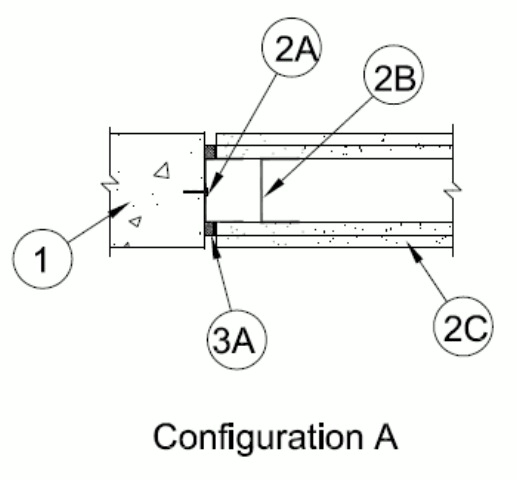
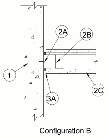
1.Wall Assembly — Min 6 in. (152 mm) thick steel-reinforced lightweight or normal weight (100-150 pcf or 1600-2400 kg/m3) structural concrete. Wall may also be constructed of any min 6 in. (152 mm) thick UL Classified Concrete Blocks*. Concrete wall may be oriented parallel to (Configuration A) or perpendicular to (Configuration B) the gypsum wall (Item 2). For Configuration A, thickness of concrete wall shall be same as or greater than the thickness of the gypsum wall.
See Concrete Blocks (CAZT) category in the Fire Resistance Directory for names of manufacturers.
2.Wall Assembly — The 1 or 2 hr fire-rated gypsum board/stud wall assembly shall be constructed of the materials and in the manner described in the individual U400, V400 Series or W400 Series Wall and Partition Design in the UL Fire Resistance Directory and shall include the following construction features:
A.Steel Runner — Runners of wall assembly shall consist of galv steel channels sized to accommodate steel studs (Item 2B) with min 1-1/4 in. (32 mm) flanges. Runner is secured to concrete wall with steel fasteners spaced max 12 in. (305 mm) OC.B.Studs — Steel studs to be min 3-1/2 in. (89 mm) wide. Studs cut 1/2 in. to 3/4 in. (13 to 19 mm) less in length than assembly height with bottom nesting in and secured to floor runner and with top nesting in ceiling runner without attachment. Stud spacing not to exceed 24 in. (610 mm) OC. First stud adjacent to concrete wall assembly shall be located maximum 4 in. (102 mm) from wall end (Configuration A) or wall face (Configuration B).C.Gypsum Board* — Gypsum board sheets installed to a min total thickness of 5/8 in. and 1-1/4 in. (16 and 32 mm) on each side of wall for 1 and 2 hr fire rated assemblies, respectively. Wall to be constructed as specified in the individual Wall and Partition Design in the UL Fire Resistance Directory, except that a max 1/2 in. (13 mm) gap shall be maintained between the side of the gypsum board and the adjacent surface of the concrete wall. The screws attaching the gypsum board to the first stud shall be located 4 in. (102 mm) from face of concrete wall. No gypsum board attachment screws shall be driven into the side runner.The hourly fire rating of the joint system is dependent on the hourly fire rating of the wall assembly in which it is installed.
3.Joint System — Max separation between side of gypsum board and face (or end) of concrete wall is 1/2 in. (13 mm) at the time of installation. The joint system is designed to accommodate a max 50 percent compression and max 100 percent extension from its installed width. The joint system consists of the following:
A.Fill, Void or Cavity Material* — Nom 1-1/2 in. (38 mm) high by 5/8 in. (16 mm) thick foam with integral 1.5 mm by 5/8 in. (16 mm) wide intumescent strip adhered to bottom surface. BlazeFoam to be compressed and inserted into joint between concrete wall and gypsum board, against side runner, with the intumescent strip positioned to rest on the cut edge of the gypsum board. BlazeFoam is supplied in varying lengths and shall be cut to length and friction fit within the joint with ends tightly butted. BlazeFoam applied within joint opening on both sides of wall.
RECTORSEAL — Blaze Foam