July 7, 2022
July 7, 2022
| ANSI/UL2079 | CAN/ULC S115 |
|---|---|
1.Floor Assembly — The fire-rated fluted steel deck/concrete floor assembly shall be constructed of the materials and in the manner described in the individual Floor-Ceiling Design in the UL Fire Resistance Directory. The hourly fire rating of the floor assembly shall be equal to or greater than the hourly fire rating of the wall assembly. The floor assembly shall include the following construction features:A.Steel Floor And Form Units* — Max 3 in. (76 mm) deep galv fluted floor units.B.Concrete — Min 2-1/2 in. (64 mm) thick reinforced (100-150 pcf or 1600-2400 kg/m3) concrete, as measured from the top plane of the floor units.
1A.Roof Assembly — As an alternate to Item 1, the fire-rated roof assembly shall be constructed of the materials and in the manner described in the individual P700, P800 or P900 Series Roof-Ceiling Designs in the UL Fire Resistance Directory and shall contain max 3 in. deep galv steel fluted roof units. The hourly fire rating of the roof assembly shall be equal to or greater than the hourly fire rating of the wall assembly. In the case of spray-applied protection materials on the steel roof units, the joint system shall be installed prior to the spray-applied protection material.
1B.Floor Assembly — As an alternate to Item 1, min 4-1/2 in. (114 mm) thick reinforced lightweight or normal weight (100-150 pcf or 1600-2400 kg/m3) structural concrete or any min 6 in. (152 mm) thick UL Classified hollow-core Precast Concrete Units*.See Precast Concrete Units (CFTV) category in the Fire Resistance Directory for names of manufactures.
2.Wall Assembly — The 1, 2 or 3 hr fire-rated gypsum board /steel stud wall assembly shall be constructed of the materials and in the manner described in the individual U400, V400 or W400-Series Wall and Partition Design in the UL Fire Resistance Directory and shall include the following construction features:A.Light Gauge Framing* — Deflection Trak — Deflection trak of wall assembly shall consist of min No. 25 gauge galv steel channels sized to accommodate steel studs (Items 2C) and with offset legs to accommodate wall cladding (Item 3A). Deflection trak installed parallel or perpendicular to the floor units. When installed perpendicular (Configuration A), min No. 25 gauge deflection trak secured on both sides to valley of floor units with 1-1/2 in. (38 mm) long welds spaced max 12 in. (305 mm) OC. Min No. 20 gauge deflection trak may be secured with No. 8 by 1/2 in. (13 mm) long steel tec screws spaced 12 in. (305 mm) OC. When installed parallel (Configuration B), min No. 25 gauge deflection trak secured on one side to valley of floor units with 1-1/2 in. (38 mm) long welds spaced 12 in. (305 mm) OC. Min No. 25 guage deflection trak may be secured with No. 8 by 1/2 in. (13 mm) steel tec screws spaced max 12 in. (305 mm) OC. The other side of the deflection trak is secured to Z-Furring clips (Item 2B) with two No. 8 by 1/2 in. (13 mm) long steel tec screws. When steel plate (Item 2F1) is used to cover flute immediately above wall oriented parallel to it, deflection trak secured to steel plate with two No. 8 self-drilling, self-tapping steel screws spaced 24in. (610 mm) OC. On concrete floor (Configuration C), min No. 20 gauge deflection trak attached to concrete at ceiling with 1/4 in. (6 mm) diam by 1-1/4 in. (32 mm) long steel expansion anchors spaced max 12 in. (305 mm) OC.
FIRE TRAK CORP — ShadowlineA1.Steel Framing Members* — Sound Isolation Clips — (Not Shown) — When wall is installed perpendicular to the floor or roof units, the sound isolation clips can be used as an alternate attachment means for the ceiling trak (Item 2A) to the bottom of the floor or roof assembly. Sound isolation clips to be installed in accordance with the accompanying installation instructions and as described herein. Sound isolation clip installed through nom 1 in. (25 mm) diam hole in ceiling trak and attached to top of ceiling trak using four min No. 8 by 1/2 in. (13 mm) long self-tapping galv steel screws. Sound isolation clips to be installed adjacent to every stud location but not more than 24 in. (610 mm) OC and attached to the underside of floor or roof assembly using min 3/16 in. (5 mm) diam by 2 1/2 in. (64 mm) long steel masonry anchors.
PAC INTERNATIONAL L L C — Type RSIC-U-HDB.Light Gauge Framing* — Slip clips shall consist of min 20 gauge galv steel and have a min width of 1-1/2 in. (38 mm). The slip clips have a formed channel that is designed to accommodate the return flange on the steel stud (Item 2C), this channel will vary with the size of steel stud that is used. They are attached to the inside bottom leg of the ceiling runner (Item 2A) with 2 - No. 8 by ½ in. (12.7 mm) long steel self-drilling framing screws and engage the return flange of the stud.
FIRE TRAK CORP — Posi KlipsC.Studs — Steel studs to be min 2-1/2 in. (64 mm) wide except that for Configuration A, when Items 3A1 and 3B1 are used, the min steel stud width is 3-5/8 in. (92 mm). In addition, steel studs to be as specified in the individual Wall and Partition Design in the UL Fire Resistance Directory. Studs cut 4 in. (012 mm) less in length than the assembly height with bottom nesting in and resting on floor runner and with top nesting in ceiling runner without attachment. Stud spacing not to exceed 24 in. (610 mm) OC.D.Framing Members* — (Not shown — Optional) — When specified in the individual U400, V400 or W400 Series Wall and Partition Design, the gypsum board on one side of the wall may be secured with furring channels and Steel Framing Members as described below:a.Furring Channels — Formed of No. 25 MSG galv steel. 2-9/16 in. or 2-23/32 in. wide by 7/8 in. deep, spaced max 24 in. OC perpendicular to studs. Channels secured to studs as described in Item b.b.Steel Framing Members* — Used to attach furring channels (Item C1a) to studs. Clips spaced max 48 in. OC. RSIC-1 and RSIC-1 (2.75) clips secured to studs with No. 8 x 1-1/2 in. minimum self-drilling, S-12 steel screw through the center grommet. Furring channels are friction fitted into clips. RSIC-1 clips for use with 2-9/16 in. wide furring channels. RSIC-1 (2.75) clips for use with 2-23/32 in. wide furring channels.
PAC INTERNATIONAL L L C — Types RSIC-1, RSIC-1 (2.75)E.Gypsum Board* — Gypsum board sheets installed and attached to studs and runners as specified in the individual Wall and Partition Design in the UL Fire Resistance Directory, except that a nominal 3-1/2 in. (89 mm) gap shall be maintained between top of the gypsum board and the bottom flange of the deflection trak. Top row of screws shall be installed into the studs, or furring channels (Item 2D), 13-1/2 in. (343 mm) below the top edge of the gypsum board sheets.F.Z-Furring — (Parallel Units) — When trak is installed parallel to floor units, Z-Furring clips are attached to the bottom of the floor units within the crests and top of the deflection trak with two No. 8 by 1/2 in. (13 mm) long steel tec screws. Clip spacing not to exceed 24 in. (610 mm) OC.
FIRE TRAK CORP — Z-Furring ClipsF1.Steel Plate — (Required for Configuration D) When wall is parallel to and directly under a flute of the floor or roof deck, a min 16MSG (0.059 in. or 1.5 mm thick) galv steel plate cut to a width to span the flute, overlapping min. 1-1/2 in. (38 mm) onto the adjacent valleys of fluted deck, shall be used for securement of the ceiling deflection track. Plate to be continuous above wall and fastened to valleys of floor or roof assembly with 1/4 in. (6 mm) diam by min 3/4 in. (19 mm) long steel actuated fasteners spaced max 24" (610 mm) OC.The hourly assembly rating of the joint system is equal to the fire rating of the wall.
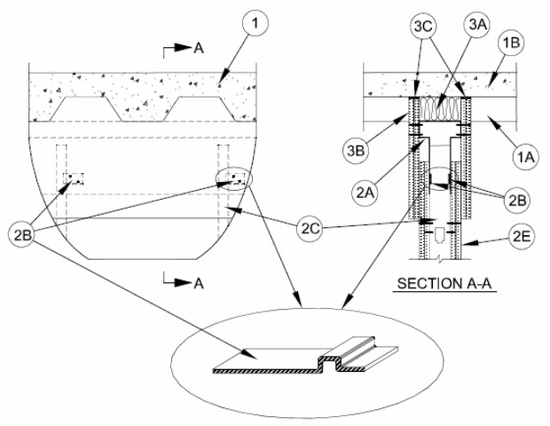
3.Joint System — Max separation between the top of bottom flange of the deflection track and top of wallboard (at the time of installation of the joint system) is between 0 and 6 in. (152 mm) in the following configurations:
Nominal Joint Width Extension Compression 0 in. (0 mm) 6 in. (152 mm) 0 in (0 mm) 1 in. (25 mm) 5 in. (127 mm) 1 in. (25 mm) 2 in. (50 mm) 4 in. (102 mm) 2 in. (50 mm) 3 in. (76 mm) 3 in. (76 mm) 3 in. (76 mm) 4 in. (102 mm) 2 in. (50 mm) 4 in. (102 mm) 5 in. (127 mm) 1 in. (25 mm) 5 in. (127 mm) 6 in. (152 mm) 0 in. (0 mm) 6 in. (152 mm) The joint system consists of packing material (Item 3A), wall cladding (Item 3B) and a fill material (Item 3C) as follows:
A.Packing Material — Min 4 pcf (64 kg/m3) density mineral wool batt insulation cut to the shape of the fluted deck, 25 percent larger than the area of the flutes and compressed into the flutes of the steel floor units above the ceiling runner as a permanent form. In addition, when sound isolation clips (Item 2A1) are used, mineral wool batt insulation, cut to a thickness 25 percent greater than the gap, shall be compressed and installed to fill the entire space between the top of the ceiling trak and the underside of the floor or roof, between and around the isolation clips, flush with both sides of the ceiling trak.A1.
Forming Material* — (Not Applicable When Sound Isolation Clips Item 2A1 Are Used) - For 1 and 2 hr Assembly, F, FT, FT and FTH Ratings, as an alternate to Item A and when Item 3B1 Wall Cladding Strips are used, min 4 pcf (64 kg/m3) density mineral wool batt insulation cut to the shape of the fluted deck, 33 percent larger than the area of the flutes and compressed into the flutes of the steel floor units above the ceiling runner as a permanent form. Mineral wool to fill entire flute and extend to be flush with exposed surface of gypsum wall cladding strips (Item 3B1) at both sides of wall. In addition and as an alternate to the sealant (Item 3C) specified for Items 3A1 and 3B1, pieces of fill material shall be applied to the maximum extent possible to fill any voids between top edge of gypsum wall cladding strips and steel floor units at any embossments within the steel deck.B.Wall Cladding — Strips of the gypsum board material cut to the contour of the steel floor units and attached to the deflection trak. The number of layers, board type and thickness and fastener type shall be specified for the gypsum board in the individual Wall and Partition Design in the UL Fire Resistance Directory. Fasteners shall be max spaced 3 in. OC. The top of the wall cladding shall be recessed min 1/8 in. (3.2 mm) to max 1/2 in. (13 mm) from the steel floor units and overlap the gypsum board 7 in. (178 mm).B1.
Wall Cladding Strips — (Not Applicable When Sound Isolation Clips Item 2A1 are Used) – For 1 and 2 hr Assembly, F, FT, FT and FTH Ratings, as an alternate to Item 3B and when Item 3A1 Forming Material is used, strips of the gypsum board material are cut to be flush with underside of valleys of the steel floor units and attached to the deflection track along length of joint. The number of layers, board type and thickness and fastener type shall be specified for the gypsum board in the individual Wall and Partition Design in the UL Fire Resistance Directory. Cladding strips are to butt tightly against underside of valleys of steel floor units and are attached to the deflection track with fasteners located in the center of the top leg and shall be max spaced 3 in. (76 mm) OC. The wall cladding strips shall overlap the gypsum board on wall (Item 2E) a min of 7 in. (178 mm). Butt joints in the wall cladding strips to be offset between layers.C.Fill, Void or Cavity Material* — When Items 3A and 3B are used, full depth of fill material installed on each side of the wall between the top of the wall cladding and the surface of the steel floor units, flush with each surface of the cladding. When Items 3A1 and 3B1 are used, fill material shall be applied to the maximum extent possible to fill any voids between top edge of gypsum wall cladding strips and steel floor units at any embossments within the steel deck (see Item 3A1 for alternate), and for L Rating, a min 3/8 in. (9.5 mm) bead of sealant shall be applied at the interface of each valley of deck to the gypsum cladding strips and at the interface of the forming material within the flutes to the steel deck.
3M COMPANY — FB 1000NS, FB 2000, FB 2000+, FD-150+, CP 25 WB+
DAP PRODUCTS INC — DAP Firestop Sealant
GRABBER CONSTRUCTION PRODUCTS INC — GrabberGard IFC, GrabberGard EFC
HILTI CONSTRUCTION CHEMICALS, DIV OF HILTI INC — CP601S, CFS-S SIL GG, CP606, FS611A or FS-ONE MAX Intumescent Sealant.
NATIONAL GYPSUM CO — FS-90
NUCO INC — Self Seal GG-200
PASSIVE FIRE PROTECTION PARTNERS — 3600EX, 4100NS, 4800DW
RECTORSEAL — Metacaulk 835+, Metacaulk 1000, Biostop 500+Caulk, Biotherm 100, FS1900, FS4000
SPECIFIED TECHNOLOGIES INC — SpecSeal ES Sealant
TREMCO INC — TREMstop Acrylic
UNITED STATES GYPSUM CO — FC, RFC
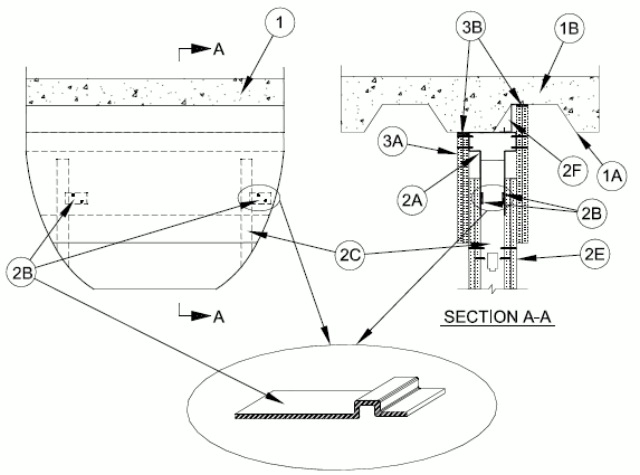
3.Joint System — Max separation between the top of bottom flange of the deflection track and top of wallboard (at the time of installation of the joint system) is between 0 and 6 in. (152 mm) in the following configurations:
Nominal Joint Width Extension Compression 0 in. (0 mm) 6 in. (152 mm) 0 in (0 mm) 1 in. (25 mm) 5 in. (127 mm) 1 in. (25 mm) 2 in. (50 mm) 4 in. (102 mm) 2 in. (50 mm) 3 in. (76 mm) 3 in. (76 mm) 3 in. (76 mm) 4 in. (102 mm) 2 in. (50 mm) 4 in. (102 mm) 5 in. (127 mm) 1 in. (25 mm) 5 in. (127 mm) 6 in. (152 mm) 0 in. (0 mm) 6 in. (152 mm) The joint system consists of wall cladding (Item 3A) and a fill material (Item 3B) as follows:
A.Wall Cladding — Strips of the gypsum board material attached to the deflection trak. The number of layers, board type and thickness and fastener type shall be as specified for the gypsum board in the individual Wall and Partition Design in the UL Fire Resistance Directory. Fasteners shall be max spaced 3 in. (76 mm) OC. The top of the wall cladding shall be recessed min 1/8 in. (3.2 mm) to max 1/2 in. (13 mm) from the steel floor units and overlap the gypsum board 7 in. (178 mm).B.Fill, Void or Cavity Material* — Full depth of fill material installed on each side of the wall between the top of the wall cladding and the surface of the steel floor units, flush with each surface of the cladding.
3M COMPANY — FB 1000NS, FB 2000, FB 2000+, FD-150+, CP 25 WB+
DAP PRODUCTS INC — DAP Firestop Sealant
GRABBER CONSTRUCTION PRODUCTS INC — GrabberGard IFC, GrabberGard EFC
HILTI CONSTRUCTION CHEMICALS, DIV OF HILTI INC — CP601S, CFS-S SIL GG, CP606 , FS611A, FS-ONE Sealant or FS-ONE MAX Intumescent Sealant.
NATIONAL GYPSUM CO — FS-90
NUCO INC — Self Seal GG-200
PASSIVE FIRE PROTECTION PARTNERS — 3600EX, 4100NS, 4800DW
RECTORSEAL — Metacaulk 835+, Metacaulk 1000, Biostop 500+Caulk, Biotherm 100, FS1900, FS4000
SPECIFIED TECHNOLOGIES INC — SpecSeal ES Sealant
TREMCO INC — TREMstop Acrylic
UNITED STATES GYPSUM CO — FC, RFC
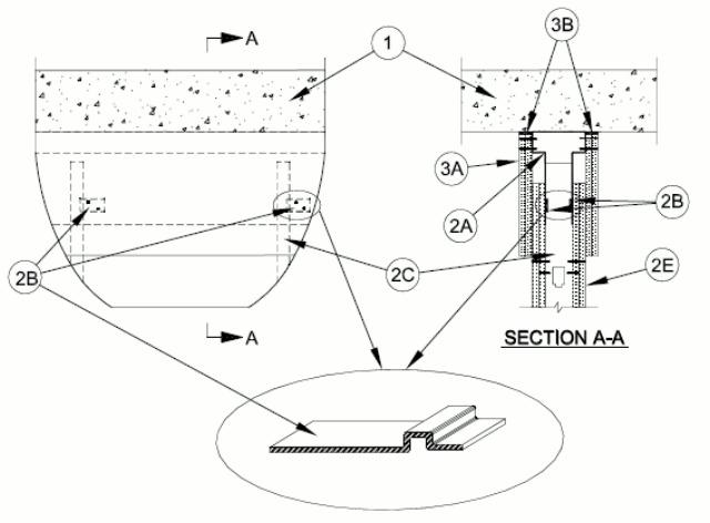
3.Joint System — Max separation between the top of bottom flange of the deflection track and top of wallboard (at the time of installation of the joint system) is between 0 and 6 in. (152 mm) in the following configurations:
Nominal Joint Width Extension Compression 0 in. (0 mm) 6 in. (152 mm) 0 in (0 mm) 1 in. (25 mm) 5 in. (127 mm) 1 in. (25 mm) 2 in. (50 mm) 4 in. (102 mm) 2 in. (50 mm) 3 in. (76 mm) 3 in. (76 mm) 3 in. (76 mm) 4 in. (102 mm) 2 in. (50 mm) 4 in. (102 mm) 5 in. (127 mm) 1 in. (25 mm) 5 in. (127 mm) 6 in. (152 mm) 0 in. (0 mm) 6 in. (152 mm) The joint system consists of wall cladding (Item 3A) and a fill material (Item 3B) as follows:
A.Wall Cladding — Strips of the gypsum board material attached to the deflection trak. The number of layers, board type and thickness and fastener type shall be as specified for the gypsum board in the individual Wall and Partition Design in the UL Fire Resistance Directory. Fasteners shall be max spaced 3 in. (76 mm) OC. The top of the wall cladding shall be recessed min 1/8 in. (3.2 mm) to max 1/2 in. (13 mm), or max 3/8 in. (9.5 mm) when Item 2A1 is used, from the bottom of the concrete floor and overlap the gypsum board 7 in. (178 mm).A1.Packing Material — (Not Shown) — When sound isolation clips (Item 2A1) are used, min 4 pcf (64 kg/m3) density mineral wool batt insulation, cut to a thickness 25 percent greater than the gap, shall be compressed and installed to fill the entire space between the top of the ceiling trak and the underside of the floor or roof, between and around the isolation clips, flush with both sides of the ceiling trak.B.Fill, Void or Cavity Material* — Full depth of fill material installed on each side of the wall between the top of the wall cladding and the bottom of the floor assembly, flush with each surface of the cladding.
3M COMPANY — FB 1000NS, FB 2000, FB 2000+, FD-150+, CP 25 WB+
DAP PRODUCTS INC — DAP Firestop Sealant
GRABBER CONSTRUCTION PRODUCTS INC — GrabberGard IFC, GrabberGard EFC
HILTI CONSTRUCTION CHEMICALS, DIV OF HILTI INC — CP601S, CFS-S SIL GG, CP606, FS611A, FS-ONE Sealant or FS-ONE MAX Intumescent Sealant.
NATIONAL GYPSUM CO — FS-90
NUCO INC — Self Seal GG-200
PASSIVE FIRE PROTECTION PARTNERS — 3600EX, 4100NS, 4800DW
RECTORSEAL — Metacaulk 835+, Metacaulk 1000, Biostop 500+Caulk, Biotherm 100, FS1900, FS4000
SPECIFIED TECHNOLOGIES INC — SpecSeal ES Sealant
TREMCO INC — TREMstop Acrylic
UNITED STATES GYPSUM CO — FC, RFC
3.Joint System — Max separation between the top of bottom flange of the deflection track and top of wallboard (at the time of installation of the joint system) is between 0 and 6 in. (152 mm) in the following configurations:
Nominal Joint Width Extension Compression 0 in. (0 mm) 6 in. (152 mm) 0 in (0 mm) 1 in. (25 mm) 5 in. (127 mm) 1 in. (25 mm) 2 in. (50 mm) 4 in. (102 mm) 2 in. (50 mm) 3 in. (76 mm) 3 in. (76 mm) 3 in. (76 mm) 4 in. (102 mm) 2 in. (50 mm) 4 in. (102 mm) 5 in. (127 mm) 1 in. (25 mm) 5 in. (127 mm) 6 in. (152 mm) 0 in. (0 mm) 6 in. (152 mm) Item 2F1 shall be used with this Configuration. The joint system consists of wall cladding (Item 3A) and a fill material (Item 3B) as follows:
A.Wall Cladding — Strips of the gypsum board material attached to the deflection trak. The number of layers, board type and thickness and fastener type shall be as specified for the gypsum board in the individual Wall and Partition Design in the UL Fire Resistance Directory. Fasteners shall be max spaced 3 in. (76 mm) OC. The top of the wall cladding shall be recessed min 1/8 in. (3.2 mm) to max 1/2 in. (13 mm), or max 3/8 in. (9.5 mm) when Item 2A1 is used, from the bottom of the concrete floor and overlap the gypsum board 7 in. (178 mm).A1.Packing Material — (Not Shown) — When sound isolation clips (Item 2A1) are used, min 4 pcf (64 kg/m3) density mineral wool batt insulation, cut to a thickness 25 percent greater than the gap, shall be compressed and installed to fill the entire space between the top of the ceiling trak and the underside of the floor or roof, between and around the isolation clips, flush with both sides of the ceiling trak.B.Fill, Void or Cavity Material* — Full depth of fill material installed on each side of the wall between the top of the wall cladding and the bottom of the floor assembly, flush with each surface of the cladding.
3M COMPANY 3M FIRE PROTECTION PRODUCTS — FB 1000NS, FB 2000, FB 2000+, FD-150+, CP 25 WB+
DAP PRODUCTS INC — DAP Firestop Sealant
GRABBER CONSTRUCTION PRODUCTS INC — GrabberGard IFC, GrabberGard EFC
HILTI CONSTRUCTION CHEMICALS, DIV OF HILTI INC — CP601S, CFS-S SIL GG, CP606, FS611A, FS-ONE Sealant or FS-ONE MAX Intumescent Sealant.
NATIONAL GYPSUM CO — FS-90
NUCO INC — Self Seal GG-200
PASSIVE FIRE PROTECTION PARTNERS — 3600EX, 4100NS, 4800DW
RECTORSEAL — Metacaulk 835+, Metacaulk 1000, Biostop 500+Caulk, Biotherm 100, FS1900, FS4000
SPECIFIED TECHNOLOGIES INC — SpecSeal ES Sealant
TREMCO INC — TREMstop Acrylic
UNITED STATES GYPSUM CO — FC, RFC