May 25, 2023
May 25, 2023
|
ANSI/UL2079 |
CAN/ULC S115 |
|
Assembly Rating—2 Hr |
F Rating — 2 Hr |
|
Nominal Joint Width— 1 In. |
FT Rating — 2 Hr |
|
Class II Movement Capabilities — 12.5% Compression or Extension |
FH Rating — 2 Hr |
|
|
FTH Rating — 2 Hr |
|
|
Nominal Joint Width— 25.4 mm. |
|
|
Class II Movement Capabilities —12.5% Compression or Extension |
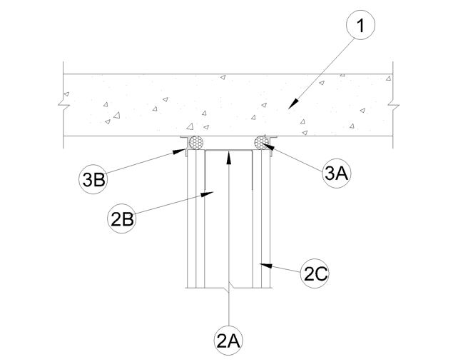
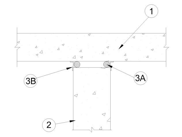
1. Floor Assembly — Min 4-1/2 in. (114 mm) thick reinforced light weight or normal weight (100-150 pcf) structural concrete.
2. Wall Assembly — The 1 or 2 hr fire rated gypsum board/steel stud wall assembly shall be constructed of the materials and in the manner described in the individual U400, V400 or W400 Series Wall and Partition Design in the UL Fire Resistance Directory and shall include the following construction features:
A. Steel Floor and Ceiling Runners — Floor and ceiling runners of wall assembly shall consist of galv steel channels sized to accommodate steel studs (Item 2B). Ceiling runner to be provided with min 1-1/4 in. (32 mm) legs. A nominal gap of 1 in. (25 mm) maintained between the top of the ceiling runner and the bottom of the floor is maintained.
B. Studs — Steel studs to be min 3-1/2 in. (89 mm) wide. Studs cut 5/8 in. (16 mm) less in length than assembly height with bottom nesting in and resting on floor runner and with top nesting in ceiling runner. Studs secured to floor runners with sheet metal screw. studs are attached to ceiling runners with sheet metal screws. When slotted ceiling runner (Item 2A1) is used, steel studs secured to slotted ceiling runner with No. 8 x 1/2 in. long wafer head steel screws at midheight of slot on each side of wall. Stud spacing not to exceed 24 in. (610 mm) OC.
C. Gypsum Board* — Gypsum board sheets installed to a min total thickness of 5/8 in. or 1-1/4 in. (16 or 32 mm) on each side of wall for 1 or 2 hr fire rated assemblies, respectively. Wall to be constructed as specified in the individual Wall and Partition Design in the UL Fire Resistance Directory, except that a nom 1 in. (25.4 mm) gap shall be maintained between the top of the gypsum board and the bottom of floor. The top row of screws shall be installed into the studs 3/4 in. (19 mm) below the top edge of the gypsum board.
2A. Wall Assembly — (As an alternate to wall assembly described in Item2) Min 6 in. (152 mm) thick reinforced lightweight or normal weight (100-150 pcf or 1600-2400 kg/m3) structural concrete. Wall may also be constructed of any UL Classified Concrete Blocks*.
See Concrete Blocks (CAZT) category in the Fire Resistance Directory for names of manufacturers.
3. Joint System — Max separation between bottom of floor and top of wall at time of installation of joint system is 1 in. (25.4 mm) The joint system is designed to accommodate a max 12.5 percent compression or extension from its installed width. The joint system consists of a packing material and a fill material, with or without a deflection channel, as follows:
A. Packing Material* — Foam backer rod sized to nominal joint width, firmly packed into gap between top of gypsum board and bottom of concrete floor as a permanent form. Forming material is to be recessed from each surface of wall to accommodate the required thickness of fill material.
B. Fill, Void or Cavity Material* — Min 1/8 in. (3.2 mm) wet thickness fill material sprayed or troweled on each side of the wall to completely cover packing material (Item 3A). Material to overlap a min of 1/2 in. (13 mm) onto wall and floor on both sides of wall. As an alternate, min 1/4 in. (6 mm) thickness of fill material sprayed or troweled on each side of the wall to completely cover packing material (Item 3A) flush on both sides of wall.