
June 22, 2023
June 22, 2023
|
ANSI/UL2079 |
CAN/ULC S115 |
|
Assembly Ratings – 1 and 2 Hr (See Item 2) |
F Ratings – 1 and 2 Hr (See Item 2) |
|
Nominal Joint Width – 1/2, 3/4 In. (See Items 2 and 3) |
FT Ratings – 1 and 2 Hr (See Item 2) |
|
Class II and III Movement Capabilities — 50% Compression and 100% Extension |
FH Ratings – 1 and 2 Hr (See Item 2) |
|
L Rating at Ambient – Less Than 1 CFM/ft |
FTH Ratings – 1 and 2 Hr (See Item 2) |
|
L Rating at 400°F – Less than 1 CFM/ft |
Nominal Joint Width – 13, 19 mm (see Items 2 and 3) |
|
|
Class II or III Movement Capabilities – 75% Compression and 25% extension or 80% compression and 30% extension (see item 3) |
|
|
L Rating at Ambient – Less Than 1.55 L/s/m |
|
|
L Rating at 203°C – Less Than 1.55 L/s/m |
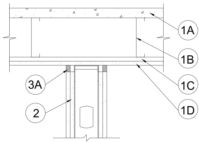
1. Floor-Ceiling Assembly — The 1 or 2 hr fire rated concrete and steel joist Floor-Ceiling assembly shall be constructed of the materials and in the manner described in the individual G500 Series Design in the UL Fire Resistance Directory, as summarized below:
A. Flooring — Lightweight or normal weight (100-150 pcf or 1600-2400 kg/m3) concrete as specified in the individual G500 Series Design.
B. Joists — Steel joists or Structural Steel Members* as specified in the individual G500 Series Design.
C. Furring Channels — Steel furring channels as specified in the individual G500 Series Design, spaced max 16 in. (406 mm) OC.
D. Gypsum Board* — Min 5/8 in. (16 mm) thick, screw-attached to furring channels as specified in the individual G500 Series Design.
The hourly rating of the joint system is equal to the lesser of the hourly ratings of the floor-ceiling assembly and the wall assembly.
2. Wall Assembly — The 1 or 2 hr fire rated gypsum board/stud wall assembly shall be constructed of the materials and in the manner described in the individual U400 or V400 Series Wall and Partition Design in the UL Fire Resistance Directory and shall include the following construction features:
A. Steel Floor and Ceiling Runners — Floor runners of wall assembly shall consist of min No. 25 gauge galv steel channels sized to accommodate steel studs (Item 2B). Floor runner to be provided with min 1-1/4 in. (32 mm) flanges. Ceiling runner installed perpendicular to furring channels (Item 1C) and secured to each furring channel through gypsum board (Item 1D) with steel fasteners specified in the individual G500 series design for the attachment of the gypsum board to the furring channels.
A1. Light Gauge Framing* — Slotted Ceiling Track — (Not Shown) — As an alternate to the Item 2A, a ceiling track consisting of galv steel channel with slotted flanges may be used. Slotted ceiling track sized to accommodate steel studs (Item 2B). Legs are to be min 1/4 in. (6 mm) longer than the maximum joint width. Attached to steel deck with steel fasteners or welds spaced max 24 in. (610 mm) OC.
B. Studs — Steel studs to be min 3-5/8 in. (92 mm) wide. Studs cut 5/8 in. to 1-1/4 in. (16 to 32 mm) less in length than assembly height with bottom nesting in and secured to floor runner. Steel studs nested in non-slotted ceiling runner without attachment or secured to slotted ceiling runner with No. 8 by 1/2 in. (13 mm) long wafer head steel screws at mid-height of slot.
C. Gypsum Board* — Gypsum board sheets installed to a min total 5/8 in. (16 mm) or 1-1/4 in. (32 mm) thickness on each side of wall for 1 and 2 hr fire rated assemblies, respectively. Wall to be constructed as specified in the individual U400 or V400 Series Design in the UL Fire Resistance Directory except that a max 1/2 in. (13 mm) gap shall be maintained between the top of the gypsum board and the bottom of the floor-ceiling assembly. The screws attaching the gypsum board to the studs along the top of the wall shall be located 4 to 5 in. (102 to 127 mm) below the bottom of the ceiling assembly. No gypsum board attachment screws shall be driven into the ceiling runner.
The hourly rating of the joint system is equal to the lesser of the hourly ratings of the floor-ceiling assembly and the wall assembly.
3. Joint System — Max separation between bottom of floor and top of wall (at time of installation of joint system) is 1/2 in. (13 mm) or 3/4 in. (19 mm) and the movement is 50% Compression and 100% Extension.
A. Fill, Void or Cavity Material* - Blaze Foam consists of nom 1-1/2 in. (38 mm) high by 5/8 in. (16 mm) thick foam with integral 5/8 in. (16 mm) wide intumescent strip adhered to bottom surface. One strip of Blaze Foam to be compressed and inserted into joint against the ceiling runner or flush with outside wall surface, between bottom of floor and top edge of gypsum board, with the intumescent strip positioned at bottom and resting on the cut edge of the gypsum board. Blaze Foam is supplied in varying lengths and shall be cut to length and friction fit within the joint with ends tightly butted. Blaze Foam applied within joint opening on both sides of wall. A layer of tape and joint compound shall be applied over the Blaze Foam for nominal joints larger than ½ in (13mm).
* Indicates such products shall bear the UL or cUL Certification Mark for jurisdictions employing the UL or cUL Certification (such as Canada), respectively.