August 4, 2023
| ANSI/UL2079 | CAN/ULC S115 |
|---|---|
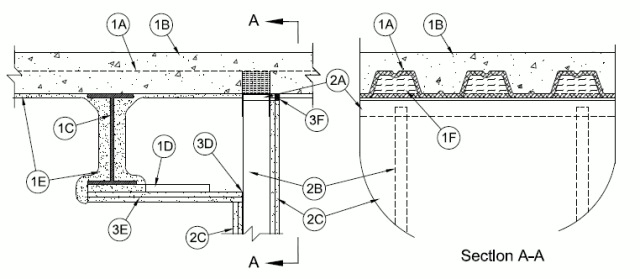
1.Floor Assembly — The fire-rated fluted steel deck/concrete floor assembly shall be constructed of the materials and in the manner described in the individual D700 Series Floor-Ceiling Design in the UL Fire Resistance Directory and shall include the following construction features:A.Steel Floor And Floor Units* — Max 3 in. (76 mm) deep galv steel fluted floor units.B.Concrete — Min 2-1/2 in. (64 mm) thick reinforced concrete, as measured from the top plane of the floor units.C.Structural Steel Support — Steel beam, as specified in the individual D700 Series Floor-Ceiling Design, used to support steel floor units. Structural steel support oriented parallel to and 1 to 12 in. (25 to 300 mm) from wall assembly.D.Steel Attachment Clips — Z-shaped clips formed from 1 in. (25 mm) wide strips of min 20 ga galv steel. Clips to be sized to extend through the thickness of the spray-applied fire-resistive material on the bottom flange of the steel beam with 1-1/2 in. (38 mm) long upper and lower legs. Legs of clips fastened to bottom of beam (prior to application of spray-applied fire-resistive materials) with steel fasteners or welds. Clips spaced max 16 in. (406 mm) OC.E.Spray-Applied Fire Resistive Material* — After installation of the steel attachment clips, structural steel support and the steel floor units structural steel support to be sprayed with the min thickness of material specified in the individual D700 Series Design. The flutes of the steel floor units are to be filled with material across the entire top flange of the steel beam. In addition, the flutes of the steel floor units immediately above the wall are to be filled with material to the full thickness of the wall (see Item 3B for alternate).
ISOLATEK INTERNATIONAL — Type 300
GCP APPLIED TECHNOLOGIES INC — Type MK-6/HY
1A.Roof Assembly — (Not Shown) — As an alternate to the floor assembly, a fire-rated fluted steel deck roof assembly may be used. The roof assembly shall be constructed of the materials and in the manner described in the individual P700 Series Roof-Ceiling Design in the UL Fire Resistance Directory. The roof assembly shall include the following construction features:A.Steel Roof Deck — Max 3 in. (76 mm) deep galv steel fluted roof deck.B.Roof Insulation — Min 2-1/4 in. (57 mm) thick poured insulating concrete, as measured from the top plane of the roof deck.C.Spray-Applied Fire Resistive Material* — After installation of the steel attachment clips, structural steel support and the steel deck to be sprayed with the min thickness of material specified in the individual P700 Series Design. The flutes of the steel deck are to be filled with material across the entire top flange of the steel beam. In addition, the flutes of the steel deck immediately above the wall are to be filled with material to the full thickness of the wall (see Item 3B for alternate).
ISOLATEK INTERNATIONAL — Type 300
GCP APPLIED TECHNOLOGIES INC — Type MK-6/HY
2.Wall Assembly — The 1 or 2 hr fire rated gypsum board/stud wall assembly shall be constructed of the materials and in the manner described in the individual U400, V400 or W400 Series Wall and Partition Design in the UL Fire Resistance Directory and shall include the following construction features:A.Steel Floor and Ceiling Tracks — Floor tracks of wall assembly shall consist of min No. 25 gauge galv steel channels sized to accommodate steel studs (Item 2B). The ceiling tracks are provided with a fill, void or cavity material and are described in Item 3A. Ceiling track installed perpendicular to direction of the fluted steel deck with typical steel fasteners max 24 in. (610 mm) OC. When optional spray applied fire resistive material is used on the steel floor units, ceiling track shall be secured through the spray-applied fire resistive material to valleys of floor unit with steel masonry fasteners spaced max 24 in. (610 mm) OC.A1.
Light Gauge Framing* — Steel Floor and Ceiling Tracks — As an alternate to steel ceiling tracks in (Item 2A), ceiling tracks are to be used with a fill, void or cavity material described in (Items 3A1, 3A2A, 3A3A, 34A, 35A, 3D1, 3D2A, 3D3A, 3D4A). Floor tracks are sized to accommodate steel studs (Item 2B). Ceiling tracks shall be installed perpendicular to direction of fluted steel deck with typical steel fasteners max 24 in. (610mm) OC.
CLARKDIETRICH BUILDING SYSTEMS — BlazeFrame DL0, SL0, DLW0, SLW0, DLX0, SLX0, DLZ0, DLY0, IAN0, ISA0, IANW0, ISAW0, IANX0, ISAX0, or IANZO SeriesB.Studs — Steel studs to be min 2-1/2 in. (64 mm) wide. Studs cut 1/2 to 1-5/8 in. (13 to 41 mm) less in length than assembly height with bottom nesting in and secured to floor track. Studs to nest in ceiling track without attachment when DL Series (Item 3) is used. When slotted ceiling track SL or DSL Series (Item 3) is used, steel studs secured to slotted ceiling track with No. 8 by 1/2 in. (13 mm) long wafer head steel screws at mid-height of exposed slot on one or both sides of slotted ceiling track.C.Gypsum Board* — Gypsum board sheets installed to a min total 5/8 in. (16 mm) or 1-1/4 in. (32 mm) thickness on each side of wall for 1 and 2 hr fire rated assemblies, respectively. Gypsum board to overlap Wall to be constructed as specified in the individual U400, V400 or W400 Series Design in the UL Fire Resistance Directory except that a max 3/8 to 1-1/2 in. (10 to 38 mm) gap shall be maintained between the top of the gypsum board and the bottom of the floor assembly on side of wall opposite beam and 3/8 to 1-1/2 in. (10 to 38 mm) gap shall be maintained between gypsum board (Item 3D) and top of wall adjacent to beam. The screws attaching the gypsum board to the studs along the top of the wall shall be located 2 in. (51 mm) below the bottom of the ceiling track and angle (Item 3C). No gypsum board attachment screws shall be driven into the ceiling track or angle.The hourly rating of the joint system is equal to the lesser of the hourly ratings of the floor/roof-ceiling assembly and the wall assembly.
3.Joint System — Max separation between bottom of floor/drywall (Item 3D) and top of gypsum board (at time of installation) is 3/8 to 1 in. (10 to 25.4 mm). The type of the fill material is dependent upon the width of the joint. The joint system is designed to accommodate a max 100 percent compression from its installed width.A.Fill, Void or Cavity Material* — Track — For nom 3/8 in. (10 mm) joints, a nom 20 ga U-shaped track having solid 2 in. (51 mm) legs or nom 20 ga J-shaped track having one 2 in. (51 mm) solid leg and one 3 in. (76 mm) slotted leg, with a nom 1 in. (25 mm) wide intumescent strip affixed to the top leg facing away from beam. Gypsum board to overlap a min of 5/8 in. (16 mm) over the intumescent strip. Ceiling track attached to steel deck with steel fasteners or welds spaced max 24 in. (610 mm) OC. When optional spray applied fire resistive material is used on the steel floor units, ceiling track shall be secured through the spray-applied fire resistive material to valleys of floor unit with steel masonry fasteners spaced max 24 in. (610 mm) OC.
CLARKDIETRICH BUILDING SYSTEMS — BlazeFrame DL1 or SL1 Series.
A1.
Fill, Void or Cavity Material* — Tape — (As an alternate to Item 3A) — For use with (Item 2A), nom 1 in. (25 mm) wide intumescent tape field applied to the top leg facing away from beam. The tape is in continuous contact with the outside surface of the legs prior to the completion of wall assembly as described by the manufacturer’s installation instructions.
CLARKDIETRICH BUILDING SYSTEMS — BlazeFrame TapeA2.
Fill, Void or Cavity Material* — Track — For nom 1/2 in. (13 mm) joints, a nom 20 ga U-shaped track having solid 2 in. (51 mm) legs or nom 20 ga J-shaped track having one 2 in. (51 mm) solid leg and one 3 in. (76 mm) slotted leg, with a nom 1-1/4 in. (32 mm) wide intumescent strip affixed to the top leg facing away from beam. Gypsum board to overlap a min of 3/4 in. (19 mm) over the intumescent strip. Ceiling track attached to steel deck with steel fasteners or welds spaced max 24 in. (610 mm) OC. When optional spray applied fire resistive material is used on the steel floor units, ceiling track shall be secured through the spray-applied fire resistive material to valleys of floor unit with steel masonry fasteners spaced max 24 in. (610 mm) OC.
CLARKDIETRICH BUILDING SYSTEMS — BlazeFrame DLW1 or SLW1 Series.
A2A.
Fill, Void or Cavity Material* — Tape — (As an alternate to Item 3A2) — For use with (Item 2A), nom 1-1/4 in. (32 mm) wide intumescent tape field applied to the top leg facing away from beam. The tape is in continuous contact with the outside surface of the legs prior to the completion of wall assembly as described by the manufacturer’s installation instructions.
CLARKDIETRICH BUILDING SYSTEMS — BlazeFrame TapeA3.
Fill, Void or Cavity Material* — For nom 3/4 in. (19 mm) joints, a nom 20 ga U-shaped track having solid 2 in. (51 mm) legs or nom 20 ga J-shaped track having one 2 in. (51 mm) solid leg and one 3 in. (76 mm) slotted leg, with a nom 1-3/4 in. (44 mm) wide intumescent strip affixed to the top leg facing away from beam. Gypsum board to overlap a min of 1 in. (25 mm) over the intumescent strip. Ceiling track attached to steel deck with steel fasteners or welds spaced max 24 in. (610 mm) OC. When optional spray applied fire resistive material is used on the steel floor units, ceiling track shall be secured through the spray-applied fire resistive material to valleys of floor unit with steel masonry fasteners spaced max 24 in. (610 mm) OC.
CLARKDIETRICH BUILDING SYSTEMS — BlazeFrame DLX1 or SLX1 Series.
A3A.
Fill, Void or Cavity Material* — Tape — (As an alternate to Item 3A3) — For use with (Item 2A), nom 1-3/4 in. (44 mm) wide intumescent tape field applied to the top leg facing away from beam. The tape is in continuous contact with the outside surface of the legs prior to the completion of wall assembly as described by the manufacturer’s installation instructions.
CLARKDIETRICH BUILDING SYSTEMS — BlazeFrame TapeA4.
Fill, Void or Cavity Material* — For nom 1 in. (25 mm) joints, a nom 20 ga U-shaped track having solid 3 in. (76 mm) legs with a nom 2-1/4 in. (57 mm) wide intumescent strip affixed to the top leg facing away from beam. Gypsum board to overlap a min of 1-1/4 in. (32 mm) over the intumescent strip. Ceiling track attached to steel deck with steel fasteners or welds spaced max 24 in. (610 mm) OC. When optional spray applied fire resistive material is used on the steel floor units, ceiling track shall be secured through the spray-applied fire resistive material to valleys of floor unit with steel masonry fasteners spaced max 24 in. (610 mm) OC.
CLARKDIETRICH BUILDING SYSTEMS — BlazeFrame DLZ1 Series.
A4A.
Fill, Void or Cavity Material* — Tape — (As an alternate to Item 3A4) — For use with (Item 2A), nom 2-1/4 in. (57 mm) wide intumescent tape field applied to the top leg facing away from beam. The tape is in continuous contact with the outside surface of the legs prior to the completion of wall assembly as described by the manufacturer’s installation instructions.
CLARKDIETRICH BUILDING SYSTEMS — BlazeFrame Tape
A5.
Fill, Void or Cavity Material* — For nom 1 in. (25.4 mm) joints, a nom 20 ga U-shaped track having solid 4 in. (102 mm) legs with a nom 3-1/4 in. (83 mm) wide intumescent strip affixed to the top leg facing away from beam. Gypsum board to overlap a min of 1-3/4 in. (44 mm) over the intumescent strip. Ceiling track attached to steel deck with steel fasteners or welds spaced max 24 in. (610 mm) OC. When optional spray applied fire resistive material is used on the steel floor units, ceiling track shall be secured through the spray-applied fire resistive material to valleys of floor unit with steel masonry fasteners spaced max 24 in. (610 mm) OC.
CLARKDIETRICH BUILDING SYSTEMS — BlazeFrame DLY1 Series.
A5A.
Fill, Void or Cavity Material* — Tape — (As an alternate to Item 3A5) — For use with (Item 2A), nom 3-1/4 in. (83 mm) wide intumescent tape field applied to the top leg facing away from beam. The tape is in continuous contact with the outside surface of the legs prior to the completion of wall assembly as described by the manufacturer’s installation instructions.
CLARKDIETRICH BUILDING SYSTEMS — BlazeFrame TapeB.Forming Material* — Min 4 pcf (64 kg/m3) density mineral wool batt insulation cut to the width of the ceiling track and to the shape of the flutes and compressed 33 percent in thickness, installed into flutes above ceiling track.
INDUSTRIAL INSULATION GROUP L L C — MinWool-1200 Safing
JOHNS MANVILLE — Safing
ROCK WOOL MANUFACTURING CO — Delta Safing Board
ROCKWOOL MALAYSIA SDN BHD — SAFE
ROXUL USA INC. D/B/A ROCKFON — SAFE
THERMAFIBER INC — SAFB1.Forming Material*-Plugs — (Not Shown) As an alternate to the forming material (Item 3A), mineral wool plugs preformed to the shape of the fluted floor units or roof deck, may be used within the flutes. Plugs shall be friction fitted to completely fill the flutes.
ROCK WOOL MANUFACTURING CO — Delta Deck PlugsC.Fill, Void or Cavity Material* - (Optional) — Min 1/8 in. (3.2 mm) wet thickness (min 1/16 in. or 1.6 mm dry thickness) of fill material sprayed or troweled on each side of the wall to completely cover mineral wool forming material and to overlap a min of 1/2 in. (13 mm) onto the steel deck surfaces on side of wall facing away from beam. When spray-applied fire resistive material is applied to the steel deck, the fill material is to overlap the spray-applied fire resistive material a min of 2 in. on side of wall facing away from the beam.
RECTORSEAL — Metacaulk 1200 spray, Metacaulk 1200 Caulk GradeD.Fill, Void or Cavity Material* — Angle — For nom 3/8 in. (10 mm) joints, a nom 20 ga L-shaped angle having min 3-1/2 in. (89 mm) vertical leg and a min 2 in. (51 mm) horizontal leg or nom 20 ga L-shaped angle having min 4-1/2 in. (114 mm) vertical slotted leg with and a min 2 in. (51 mm) horizontal leg with a nom 1 in. (25 mm) wide intumescent strip affixed to the vertical leg 1-1/4 in. (32 mm) below the horizontal leg facing the finished side. Composite angle attached to the bottom of the steel attachment clips with typical steel fasteners. Gypsum board to overlap a min of 5/8 in. (16 mm) over the intumescent strip.
CLARKDIETRICH BUILDING SYSTEMS — BlazeFrame IAN or ISA Series
D1.
Fill, Void or Cavity Material* — Tape — (As an alternate to Item 3D) — For use with (Item 2A1), nom 1 in. (25 mm) wide intumescent tape field applied to the vertical leg 1-1/4 in. (32 mm) below the horizontal leg facing the finished side. The tape is in continuous contact with the outside surface of the leg prior to the completion of wall assembly as described by the manufacturer’s installation instructions.
CLARKDIETRICH BUILDING SYSTEMS — BlazeFrame TapeD2.Fill, Void or Cavity Material* — Angle — For nom 1/2 in. (13 mm) joints, a nom 20 ga L-shaped angle having min 3-1/2 in. (89 mm) vertical leg and a min 2 in. (51 mm) horizontal leg or nom 20 ga L-shaped angle having min 4-1/2 in. (114 mm) vertical slotted leg with and a min 2 in. (51 mm) horizontal leg with a nom 1 1/4 in. (32 mm) wide intumescent strip affixed to the vertical leg 1-1/4 in. (32 mm) below the horizontal leg facing the finished side. Composite angle attached to the bottom of the steel attachment clips with typical steel fasteners. Gypsum board to overlap a min of 3/4 in. (19 mm) over the intumescent strip.
CLARKDIETRICH BUILDING SYSTEMS — BlazeFrame IANW or ISAW Series
D2A.
Fill, Void or Cavity Material* — Tape — (As an alternate to Item 3D2) — For use with (Item 2A1), nom 1-1/4 in. (32 mm) wide intumescent tape field applied to the vertical leg 1-1/4 in. (32 mm) below the horizontal leg facing the finished side. The tape is in continuous contact with the outside surface of the leg prior to the completion of wall assembly as described by the manufacturer’s installation instructions.
CLARKDIETRICH BUILDING SYSTEMS — BlazeFrame TapeD3.
Fill, Void or Cavity Material* — Angle — For nom 3/4 in. (19 mm) joints, a nom 20 ga L-shaped angle having min 3-1/2 in. (89 mm) vertical leg and a min 2 in. (51 mm) horizontal leg or nom 20 ga L-shaped angle having min 5 in. (127 mm) vertical slotted leg with and a min 2 in. (51 mm) horizontal leg with a nom 1-3/4 in. (44 mm) wide intumescent strip affixed to the vertical leg 1-1/4 in. (32 mm) below the horizontal leg facing the finished side. Composite angle attached to the bottom of the steel attachment clips with typical steel fasteners. Gypsum board to overlap a min of 1 in. (25 mm) over the intumescent strip.
CLARKDIETRICH BUILDING SYSTEMS — BlazeFrame IANX or ISAX Series
D3A.
Fill, Void or Cavity Material* — Tape — (As an alternate to Item 3D3) — For use with (Item 2A1), nom 1-3/4 in. (44 mm) wide intumescent tape field applied to the vertical leg 1-1/4 in. (32 mm) below the horizontal leg facing the finished side. The tape is in continuous contact with the outside surface of the leg prior to the completion of wall assembly as described by the manufacturer’s installation instructions.
CLARKDIETRICH BUILDING SYSTEMS — BlazeFrame TapeD4.Fill, Void or Cavity Material* — Angle —For nom 1 in. (25 mm) joints, a nom 20 ga L-shaped angle having min 3-1/2 in. (89 mm) vertical leg and a min 2 in. (51 mm) horizontal leg with a nom 2-1/4 in. (56 mm) wide intumescent strip affixed to the vertical leg 1-1/4 in. (32 mm) below the horizontal leg facing the finished side. Composite angle attached to the bottom of the steel attachment clips with typical steel fasteners. Gypsum board to overlap a min of 1-1/4 in. (56 mm) over the intumescent strip.
CLARKDIETRICH BUILDING SYSTEMS — BlazeFrame IANZ Series
D4A.
Fill, Void or Cavity Material* — Tape — (As an alternate to Item 3D4) — For use with (Item 2A1), nom 2-1/4 in. (45 mm) wide intumescent tape field applied to the vertical leg 1-1/4 in. (32 mm) below the horizontal leg facing the finished side. The tape is in continuous contact with the outside surface of the leg prior to the completion of wall assembly as described by the manufacturer’s installation instructions.
CLARKDIETRICH BUILDING SYSTEMS — BlazeFrame TapeE.Gypsum Board* — Gypsum board sheets installed on underside of steel attachment clips (Item 1D) to a min total 5/8 in. (16 mm) or 1-1/4 in. (32 mm) thickness for 1 and 2 hr fire rated assemblies, respectively. Gypsum boards installed to completely cover the gap between steel beam and wall and secured to each steel attachment clips with a minimum of two steel drywall screws approximately 1 to 2 in. (25 to 51 mm) from each end of the clip.F.Fill, Void or Cavity Material* — L-Bead is to be installed on both sides of wall. L-Bead horizontal flange to be applied over the top face of the gypsum base, ensuring horizontal and vertical flanges are in contact gypsum base. Splices are cut square aligned and tightly butted together. Attach L-Bead to the gypsum base with 9/16 in (14 mm) type G staples, or equivalent, spaced 12 in. (305 m) o.c. maximum along the flange in accordance with supplied manufacturers supplied instructions.
CLARKDIETRICH BUILDING SYSTEMS — BlazeFrame Perimeter L-BeadF1.Packing Material — (As an alternate to 3F) Open cell polyurethane backer rod foam having a density of 1.5 to 2.0 pcf (24 to 32 kg/m3). Min 5/8 in. (16 mm) or 1 in. (25.4 mm) thickness of material for 1 and 2 hr rated walls, respectively, shall be firmly packed into the joint at both sides of wall as a permanent form. Backer rod shall be installed flush with both sides of wall to accommodate installation of Item 3G.G.Tape and Joint Compound — (As an alternate to Item 3F must be used with Item 3F1) A layer of tape and joint compound shall be applied over the backer rod packing material with the tape lapping onto the wall only.