HW-D-0716
May 28, 2014
May 28, 2014
| ANSI/UL2079 | CAN/ULC S115 |
|---|---|
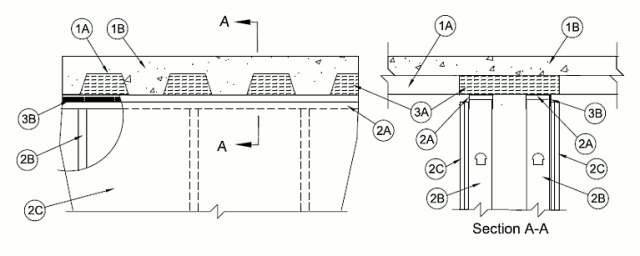
1.Floor Assembly — The fire-rated fluted steel deck/concrete floor assembly shall be constructed of the materials and in the manner described in the individual D900 Series Floor-Ceiling Design in the UL Fire Resistance Directory and shall include the following construction features:
A.Steel Floor And Form Units* — Max 3 in. (76 mm) deep galv steel fluted floor units.B.Concrete — Min 2-1/2 in. (64 mm) thick reinforced concrete, as measured from the top plane of the floor units.
1A.Roof Assembly — (Not Shown) - As an alternate to the floor assembly, a fire rated fluted steel deck roof assembly may be used. The roof shall by constructed of the materials and in the manner described in the individual P900 Series Roof-Ceiling designs in the UL Fire Resistance Directory. The hourly rating of the roof assembly shall be equal to or greater than the hourly rating of the wall assembly. The roof assembly shall include the following construction features:
A.Steel Roof Deck — Max 3 in. (76 mm) deep galv steel fluted roof deck.B.Roof Insulation — Roof insulation to consist of min 2 1/4 in. (57 mm) thick poured insulating concrete, as measured from the top plane of the roof deck.
2.Chase Wall Assembly — The 1 or 2 hr fire rated gypsum board/stud chase (double stud) wall assembly shall be constructed of the materials and in the manner described in the individual U400, V400 or W400 Series Wall and Partition Design in the UL Fire Resistance Directory and shall include the following construction features:
A.Steel Floor and Ceiling Runners — Channel shaped ceiling runner with width to accommodate studs, legs of min 2 in. (51 mm), and fabricated from min 24 MSG galv steel. Ceiling runner installed perpendicular to steel deck direction. Floor runners of wall assembly shall consist of min No. 25 ga galv steel channels sized to accommodate the steel studs. Floor runner to be provided with min 1-1/4 in. (32 mm) flanges. Ceiling runner to be attached to steel deck with steel fasteners spaced a max of 24 in. (610 mm) O.C.B.Studs — Steel studs to be min 3-1/2 in. (89 mm) wide and formed of min 25 ga galv steel. Studs cut 3/4 to 1 in. (19 to 25 mm) less in length than assembly height with bottom nesting in and secured to floor runner. Steel studs nested in ceiling runner without attachment. Studs spaced max 24 in. (610 mm) OC.C.Gypsum Board* — Gypsum board 1/2 or 5/8 in. (13 or 16 mm) thick, applied on both sides of wall as specified in the individual Wall and Partition Design except that a max 1/2 in. (13 mm) gap shall be maintained between the top of the gypsum board and the bottom of the floor assembly. The screws attaching the gypsum board to the studs along the top of the wall shall be located 3 to 3-1/2 in. (76 to 89 mm) down from deck at time of installation. No gypsum board attachment screws shall be driven into the ceiling runner.The hourly fire rating and the F, FT. FH and FTH ratings of the joint system are equal to the hourly fire rating of the wall.
3.Joint System — Max separation between bottom of floor and top of gypsum board (at time of installation) is 1/2 in. (13 mm). The joint system is designed to accommodate a max 100 percent compression or extension from its installed width. The joint system shall consist of the following:
A.Forming Material* — Min 4 pcf (64 kg/m3) mineral wool insulation cut to the shape of the fluted steel floor units, approx 33% larger than the area of the flutes. Pieces compressed and inserted into the flutes above the top ceiling runners extending the full thickness of the double stud wall and flush with gypsum board on both sides of wall.See Forming Material (XHKU) category in the Fire Resistance Directory for names of manufacturers.A1.Forming Material* - Plugs — (Not Shown) - As an alternate to the forming material Item, mineral wool plugs preformed to the shape of the fluted floor units may be used within the flutes. Plugs shall be friction fit to completely fill the flutes above the ceiling runners across the full thickness of the double stud wall and flush with the gypsum board on both sides of wall.
ROCK WOOL MANUFACTURING CO — Deck PlugsB.Fill, Void or Cavity Material* — Min 25 ga composite steel angle with one 5/8 in. (16 mm) leg and one 1-1/2 in (38 mm) leg with an intumescent strip affixed along the inside 1-1/2 in (38 mm) leg. The 5/8 in. leg of steel angle is friction fit between the top web of one ceiling runner and the steel deck. Steel angle is required on one side of wall only (either side).
RECTORSEAL — Track SafeC.Fill, Void or Cavity Material* — Min 1/8 in. (3 mm) wet thickness (min 1/16 in. or 1.6 mm dry thickness) of fill material spray applied over the forming material in flutes on one side of wall (either side). Fill material to overlap min 1/2 in. (13 mm) onto steel floor or roof deck and ceiling runner or steel angle (Item 3B).
RECTORSEAL — Metacaulk 1200 Spray, Metacaulk 1500 Spray, Biostop 750 Spray, Biostop 800 Spray, FlameSafe FS3000 Spray