June 26, 2023
1.Floor Assembly — The fire-rated fluted steel deck/concrete floor assembly shall be constructed of the materials and in the manner described in the individual D700 or D900 Series Floor-Ceiling Design in the UL Fire Resistance Directory and shall include the following construction features:A.Steel Floor And Floor Units* — Max 3 in. (76 mm) deep galv steel fluted floor units.B.Concrete — Min 2-1/2 in. (64 mm) thick lightweight or normal weight (100-150 pcf or 1600-2400 kg/m3) reinforced concrete, as measured from the top plane of the floor units.C.Spray-Applied Fire Resistive Material* — (Optional, Not Shown) - Prior to the installation of the joint system (Item 3) all surfaces of the steel floor units to be sprayed with the thickness of material specified in the individual D700 Series Design.
GCP APPLIED TECHNOLOGIES INC — Type MK-6/HY, MK-6/HY ES, RG and MK-6S
1A.Roof Assembly — (Not Shown) — As an alternate to the floor assembly, a fire-rated fluted steel deck roof assembly may be used. The roof assembly shall be constructed of the materials and in the manner described in the individual P700 or P900 Series Roof-Ceiling Design in the UL Fire Resistance Directory. The roof assembly shall include the following construction features:A.Steel Roof Deck — Max 3 in. (76 mm) deep galv steel fluted roof deck.B.Roof Insulation — For P900 Series Designs, min 2-1/4 in. (57 mm) thick poured insulating concrete, as measured from the top plane of the roof deck. For P700 Series Designs, roof insulation shall be as specified in the individual design.C.Spray-Applied Fire Resistive Material* — (Optional, Not Shown) - Prior to the installation of the joint system (Item 3) all surfaces of the roof deck to be sprayed with the thickness of material specified in the individual P700 Series Design.
GCP APPLIED TECHNOLOGIES INC — Type MK-6/HY, MK-6/HY ES, RG and MK-6S
The hourly fire rating of the floor or roof assembly shall be equal to or greater than the hourly fire rating of the wall assembly.
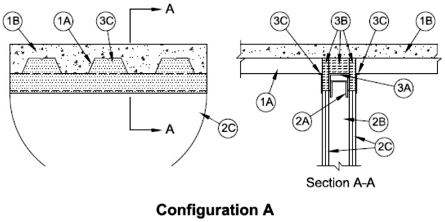
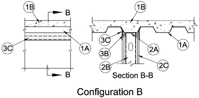
2.Wall Assembly — The max separation between bottom of steel floor units, roof deck or spray-applied fire resistive material (if used) and top of wall (at time of installation of joint system) is dependent upon the type of floor or roof assembly, hourly rating of the wall and configuration of the joint system, as shown in table under Item 3. Wall may be perpendicular to direction of the fluted steel floor units or roof deck (Configuration A) or parallel to and centered under the valleys of the steel floor units or roof deck (Configuration B). The 1, 2, 3 or 4 hr fire-rated gypsum board/stud wall assembly shall be constructed of the materials and in the manner described in the individual U400 or V400 Series Wall and Partition Design in the UL Fire Resistance Directory and shall include the following construction features:A.Steel Floor and Ceiling Runners — Floor and ceiling runners of wall assembly shall consist of min No. 25 gauge galv steel channels sized to accommodate steel studs (Item 2B). Ceiling runner to be provided with min 1-1/4 in. (32 mm) flanges. Studs and gypsum board must have a min 1/4 in. (6 mm) engagement onto the flanges of the ceiling runner at the furthest point of extension of the joint. When U shaped deflection channel is used, ceiling runner is installed within the U-shaped deflection channel (Item 3B) with 1 in. (25 mm) gap maintained between the top of ceiling runner and top of deflection channel. When deflection channel is not used, ceiling runner installed perpendicular to or parallel with direction of the fluted steel deck prior to the application of the spray-applied fire resistive material (if used). Ceiling runner secured to steel deck valleys with steel masonry anchors or welds spaced max 24 in. (610 mm) OC.A1.Light Gauge Framing* — Slotted Ceiling Runner — When the nom joint width is less than or equal to 1-3/4 in. (44 mm) or when the thickness of the spray-applied fire resistive material is less than 1 in. (25 mm), slotted ceiling runner may be used as an alternate to the ceiling runner in Item 2A. Slotted ceiling runner to consist of galv steel channel with slotted flanges sized to accommodate steel studs (Item 2B). Slotted ceiling runner installed perpendicular to or parallel with direction of fluted steel deck prior to the application of the spray-applied fire resistive material (if used). Slotted ceiling runner secured to steel deck valleys with steel masonry anchors spaced max 24 in. (610 mm) OC. When slotted ceiling runner is used, deflection channel (Item 3a) shall not be used.
BRADY CONSTRUCTION INNOVATIONS INC, DBA SLIPTRACK SYSTEMS — SLP-TRK
CEMCO, LLC — CST
CLARKDIETRICH BUILDING SYSTEMS — Type SLT, SLT-H
METAL-LITE INC — The System
SCAFCO STEEL STUD MANUFACTURING CO
TELLING INDUSTRIES L L C — True-Action Deflection TrackA2.Light Gauge Framing* — Clipped Ceiling Runner — As an alternate to the ceiling runner in Item 2A, clipped runner to consist of galv steel channel with clips preformed in track flanges which positively engage the inside flange of the steel studs (Item 2B). Track sized to accommodate steel studs (Item 2B). Track flanges to be min 3 in. (76 mm). Clipped ceiling runner installed perpendicular to or parallel with direction of fluted steel deck prior to the application of the spray-applied fire resistive material (if used). Clipped ceiling runner secured to steel deck valleys with steel masonry anchors spaced max 24 in. (610 mm) OC. When clipped ceiling runner is used, deflection channel (Item 3A) shall not be used.
TOTAL STEEL SOLUTIONS L L C — Snap TrakA3.Light Gauge Framing* —Vertical Deflection Clip — (Optional) Steel clips can be used in conjunction with steel studs (Item 2B), ceiling runner (Item 2A) or deflection channel (Item 3A). Clips installed over the top of studs and inserted within the ceiling runner or deflection channel. Clip shall be secured to the ceiling runner or deflection channel with No. 8 self drilling, self tapping steel fasteners through holes provided within the clip. Clip may be secured to the stud with No. 6 pan head steel screw through holes provided within the clip. As an alternate, the legs of the clip may be installed over the top of the stud without attachment in accordance with manufacturer's installation instructions.
FLEX-ABILITY CONCEPTS L L C — Three Legged Dog Deflection ClipA4.Light Gauge Framing*- Notched Ceiling Runner — As an alternate to the ceiling runners in Items 2A through 2A3, notched ceiling runners to consist of C-shaped galv steel channel with notched return flanges sized to accommodate steel studs (Item 2B). Notched ceiling runner installed perpendicular to or parallel with direction of fluted steel deck and secured to steel deck valleys with steel masonry anchors spaced max 24 in. (610 mm) OC. When notched ceiling runner is used, deflection channel (Item 3A) shall not be used.
OLMAR SUPPLY INC — Type SCRB.Studs — Steel studs to be min 3-5/8 in. (92 mm) wide. Studs cut 3/4 in. (19 mm) less in length than assembly height with bottom nesting in and resting on floor runner and with top nesting in ceiling runner without attachment. Studs and gypsum board must have a min 1/4 in. (6 mm) engagement onto the flanges of the ceiling runner at the furthest point of extension of the joint. When slotted ceiling runner (Item 2A1) is used, steel studs secured to slotted ceiling runner with No. 8 by 1/2 in. (13 mm) long wafer head steel screws at midheight of slot on each side of wall. Stud spacing not to exceed 24 in. (610 mm) OC.C.Gypsum Board* — Gypsum board sheets installed to a min total thickness of 5/8 in., 1-1/4 in., 1-1/2 in. or 2 in. (16, 32, 38 or 51 mm) on each side of wall for 1, 2, 3 and 4 hr fire rated wall assemblies, respectively. Wall to be constructed as specified in the individual U400 or V400 Series Wall and Partition Design in the UL Fire Resistance Directory, except that a max 1-1/2 or 2 in. (38 or 51 mm) gap shall be maintained between the top of the gypsum board and the bottom surface of the steel floor units or roof deck as specified in Item 3 below. The top row of screws shall be installed into the studs 4-3/4 in. (121 mm) below the valleys of the steel floor units, roof deck or spray-applied fire resistive material (if used).The hourly fire rating of the joint system is equal to the hourly fire rating of the wall.
3.Joint System — Max separation between bottom of floor and top of wall (at time of installation of joint system) is dependent upon the hourly rating of the wall, type of assembly, and configuration of joint system. The joint system is designed to accommodate a max 25 percent compression or extension from it's installed width. The hourly rating of the joint system is dependent upon the joint configuration, type of floor or roof assembly, max hourly rating of the wall assembly and max width of the joint as shown in the table below:
Type of
AssemblyRating of Wall
Assembly, HrJoint
ConfigurationMax Joint
Width, In (mm)Hourly Rating,
HrD900 or P900 1, 2, 3 & 4 A 1-1/2 or 2 (38 or 51) 1, 2, 3 & 4 D900 or P900 1 & 2 B 1-1/2 or 2 (38 or 51) 1 & 2 D700 or P700 1, 2 & 3 A 1 (25) 1, 2 & 3 D700 or P700 1 & 2 B 1 (25) 1 & 2 The joint system consists of a deflection channel, forming material and fill material, as follows:
Joint Configuration A For unprotected steel floors units or roof decks (D900 or P900 Series Designs), max separation between bottom of floor or roof and top of wall (at time of installation of joint system) is 1-1/2 in. (38 mm) for 1 hr fire rated assemblies and 2 in. (51 mm) for 2, 3 and 4 hr fire rated assemblies. For protected steel floors units or roof decks (D700 or P700 Series Designs), max separation between bottom of spray-applied fire resistive material and top of wall (at time of installation of joint system) is 1 in. (25 mm).
A.Deflection Channel — (Optional) - Nom 3-3/4 in. (95 mm) wide by 3 in. (76 mm) deep U-shaped channel formed from min 25 gauge galv steel. Deflection channel installed perpendicular to direction of the fluted steel deck and secured to the steel deck valleys with steel masonry anchors or by welds spaced max 12 in. (305 mm) OC. The ceiling runner (Item 2A) is installed within the deflection channel to maintain a 1 in. (25 mm) gap between the top of the ceiling runner and the top of the deflection channel. The ceiling runner is not fastened to the deflection channel.B.Forming Material* — Min 4-7/8 in., 6 in., 6-5/8 in. or 7-5/8 in. (124, 152, 168 or 194 mm) depth of 4 pcf (64 kg/m3) mineral wool batt insulation for 1, 2, 3 and 4 hr fire rated assemblies, respectively, cut to the shape of the fluted deck, approx 25 percent larger than the area of the flutes and compressed into the fluted area of the steel floor or roof deck above the ceiling channel. Additional strips of min 4 pcf (64 kg/m3) density- mineral wool batt insulation cut to a thickness equal to the overall thickness of the gypsum board, are compressed 50 percent in thickness and installed cut edge first to fill the gap between the top of the gypsum board and bottom of the steel floor units or roof deck. The forming material shall be installed flush with both surfaces of the wall.The type and manufacturer of forming material used within the joint system is dependent upon the hourly rating of the wall assembly as shown in the table below:
Rating of Wall,
hrManufacturer of Mineral Wool Type of Mineral
Wool1, 2, & 3 Fibrex Insulation Inc FBX Safing Insulation 1, 2, 3, & 4 Roxul Inc SAFE Mineral Wool 1 & 2 Rock Wool Manufacturing Delta Safing Insulation 1, 2 & 3 Thermafiber Inc SAF
ROCK WOOL MANUFACTURING CO — Delta Safing Insulation
ROCKWOOL MALAYSIA SDN BHD — SAFE Mineral Wool Batts
ROCKWOOL — SAFE Mineral Wool Batts
THERMAFIBER INC — SAFB1.Spray-Applied Fire Resistive Material* (Not Shown) — As an alternate to the forming material (Item 3A) within the flutes, min 4-7/8 in., 6 in., 6-5/8 in., or 7-5/8 in. (124, 152, 168 or 194 mm) depth of spray-applied fire resistive material, for 1, 2, 3, and 4 hr fire rated assemblies, respectively, installed into the flutes of the steel floor or roof deck between the top of the wall and the bottom of the steel floor units or roof deck. Material shall be excluded from the joint immediately above the top of the gypsum board assemblies. The spray-applied fire resistive material is mixed with water in accordance with the mixing instructions on the bag and is sprayed and/or troweled to fill the flute above the wall. The min average density of the spray applied fire resistive material shall be 15 pcf (240 kg/m3) with a min individual density of 14 pcf. (224 kg/m3). See Design Information in Volume 1 of the Fire Resistance Directory for method of density determination.
GCP APPLIED TECHNOLOGIES INC — Types MK-6/HY, MH-6/HY ES, RG, MK-6s, Z-106/G, Z-106, Z-106/HY and Z-146.B2.Forming Material* - Plugs — (Not Shown) As an alternate to the forming material and spray-applied fire resistive material (Items 3B and 3B1), mineral wool plugs preformed to the shape of the fluted floor units, may be used within the flutes. Plugs shall be friction fit to completely fill the flutes above the ceiling channel. The plugs shall project beyond each side of the ceiling runner, flush with wall surfaces. Additional forming material, described in Item 3B, to be used in conjunction with the plugs to fill the gap between the top of gypsum board and bottom of steel floor units or roof deck. Plugs to be used in max 2 hr fire rated wall assemblies.
ROCK WOOL MANUFACTURING CO — Deck PlugsC.Fill, Void or Cavity Material* — Sealant — For assemblies incorporating mineral wool insulation within the flutes, min 1/8 in. (3 mm) wet thickness of fill material spray or brush applied on each side of the wall in the fluted area of the steel floor units or roof decks and between the top of the wall and the bottom of the steel floor units roof deck. Sealant shall overlap a min 1/2 in. (13 mm) onto wall and steel floor units or roof deck on both sides of wall or spray-applied fire resistive material, if used. For assemblies incorporating spray-applied fire resistive materials within the flutes, min 1/8 in. (3 mm) wet thickness of fill material spray or brush to cover the mineral wool insulation within the joint between the top of the wall and the bottom of the steel floor units roof decks. Sealant shall overlap a min 1/2 in. (13 mm) onto wall and a min 1/2 in. (13 mm) above the joint onto the spray-applied fire resistive material within the flutes on both sides of wall. When optional through penetrant (Item 4) is used, fill material to overlap a min of 1/2 in. (13 mm) onto conduit or EMT on both sides of wall.
RECTORSEAL — Metacaulk 1200 Spray, Metacaulk 1200 Caulk GradeJoint Configuration B For unprotected steel floor units or roof decks (D900 or P900 Series Designs), max separation between bottom of floor or roof and top of wall (at time of installation of joint system) is 1-1/2 and 2 in. (38 and 51 mm) for 1 and 2 hr fire rated assemblies, respectively. For protected steel floor units or roof decks (D700 or P700 Series Designs), max separation between bottom of spray-applied fire resistive material and top of wall (at time of installation of joint system) is 1 in. (25 mm).
A.Deflection Channel — Nom 3-3/4 in. (95 mm) wide by 3 in. (76 mm) deep U-shaped channel formed from min No. 22 ga galv steel. Deflection channel centered on valley of steel floor or roof deck and secured with steel fasteners or by welds spaced max 12 in. (305 mm) OC (prior to application of spray-applied fire resistive material, if used). The ceiling runner (Item 2A) is installed within the deflection channel to maintain a 1 in. (25 mm) gap between the top of the ceiling runner and the top of the deflection channel. The ceiling runner is not fastened to the deflection channel.B.Forming Material* — Strips of min 4 pcf (64 kg/m3) mineral wool batt insulation, cut to a thickness equal to the overall thickness of the gypsum board and compressed 50 percent in width. Mineral wool strips inserted into the gap between the top of the gypsum board and bottom of the steel floor units, roof deck or spray-applied fire resistive material, (if used), flush with both surfaces of the wall.The type and manufacturer of forming material used within the joint system is dependent upon the hourly rating of the wall assembly as shown in the table below:
Rating of
Wall, hrManufacturer of
Mineral WoolType of
Mineral Wool1, 2 & 3 Fibrex Insulation Inc FBX Safing Insulation 1, 2 & 3 Roxul Inc. SAFE Mineral Wool 1 & 2 Rock Wool Manufacturing Delta Safing Insulation 1, 2 & 3 Thermafiber Inc SAF
ROCK WOOL MANUFACTURING CO — Delta Safing Insulation
ROCKWOOL MALAYSIA SDN BHD — SAFE Mineral Wool Batts
ROCKWOOL — SAFE Mineral Wool Batts
THERMAFIBER INC — SAFC.Fill, Void or Cavity Material* — Min 1/8 in. (3 mm) wet thickness of fill material spray or brush applied on each side of the wall to completely cover mineral wool forming material and to overlap a min of 1/2 in. (13 mm) onto gypsum board and steel floor units, roof deck or spray-applied fire resistive material, if used on both sides of wall.
RECTORSEAL — Metacaulk 1200 Spray, Metacaulk 1200 Caulk Grade
4.Through Penetrant — (Optional, Not Shown) - Max 1-1/2 in. (38 mm) diam steel conduit or steel electrical metallic tubing (EMT) may be installed parallel with and within the flutes of the steel floor or roof deck when Joint Configuration A is used. The conduit or EMT shall be located near the mid-depth of the steel deck with a clearance of 1/2 to 1-1/2 in. (13 to 38 mm) between the conduit or EMT and the steel deck. Conduit or EMT to be rigidly supported on both sides of the wall assembly. A max of one conduit or EMT is permitted in an individual flute. When a conduit or EMT is installed in the flute of the steel deck, the max assembly rating of the joint system is 2 hr.