
June 20, 2023
| ANSI/UL2079 | CAN/ULC S115 |
|---|---|
| L Rating at Ambient – Less Than 1 CFM/Lin Ft | |
| L Rating at 400°F – Less Than 1 CFM/Lin Ft |
Nominal Joint Width — 6, 10, 13, 16, 19, or 25 mm(see Item 2 and 3) |
|
Class II or III Movement Capabilities — 100% Compression or Extension See Table 1 |
|
| L Rating at Ambient – Less Than 1.55 L/s/m | |
| L Rating at 204°C – Less Than 1.55 L/s/m |
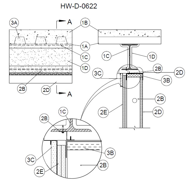
1.Floor Assembly — The fire-rated fluted steel deck/concrete floor assembly shall be constructed of the materials and in the manner described in the individual D700or D900 Series Floor-Ceiling Design in the UL Fire Resistance Directory and shall include the following construction features:A.Steel Floor And Form Units* — Max 3 in. (76 mm) deep galv steel fluted floor units.B.Concrete — Min 2-1/2 in. (64 mm) thick reinforced concrete, as measured from the top plane of the floor units.C.Structural Steel Support — Steel beam, as specified in the individual D700 or D900 Series Floor-Ceiling Design, used to support steel floor units. Steel Beam centered over and parallel with wall assembly.D.Spray-Applied Fire Resistive Material* — After installation of the steel attachment clips (Item 2B), steel floor units, and ceiling runner (Item 3), all surfaces of the steel floor units and structural steel support to be sprayed with the thickness of material specified in the individual D700 or D900 Series Floor-Ceiling Design. The flutes of the steel floor units are to be filled with material across the entire top flange of the steel beam. The areas between the bottom flange of the structural support and top of the ceiling runner are to be filled entirely with material. Additional material shall be applied to the web of the steel beam on each side of the wall. The thickness of material applied to each side of the steel beam web shall be 2 in. (51 mm).
ISOLATEK INTERNATIONAL — Type 300
GCP APPLIED TECHNOLOGIES INC — Type MK-6/HY
1A.Roof Assembly — (Not Shown) - As an alternate to the floor assembly, a fire rated fluted steel deck roof assembly may be used. The roof shall by constructed of the materials and in the manner described in the individual P700 or P900-Series Roof-Ceiling designs in the UL Fire Resistance Directory. The hourly rating of the roof assembly shall be equal to or greater than the hourly rating of the wall assembly. The roof assembly shall include the following construction features:A.Steel Roof Deck — Max 3 in. (76 mm) deep galv steel fluted roof deck.B.Roof Insulation — Roof insulation to consist of min 2-1/4 in. (57 mm) thick poured insulating concrete, as measured from the top plane of the roof deck.C.Structural Steel Support — Steel Beam, as specified in the individual P700 or P900 Series Floor-Ceiling Design, used to support steel floor units. Steel Beam centered over and parallel with wall assembly.D.Spray-Applied Fire Resistive Material* — After installation of the steel attachment clips (Item 2B), steel floor units, and ceiling runner (Item 3), all surfaces of the steel floor units and structural steel support to be sprayed with the thickness of material specified in the individual P700 or P900 Series Floor-Ceiling Design. The flutes of the steel floor units are to be filled with material across the entire top flange of the steel beam. The areas between the bottom flange of the structural support and top of the ceiling runner are to be filled entirely with material. Additional material shall be applied to the web of the steel beam on each side of the wall. The thickness of material applied to each side of the steel beam web shall be 2 in. (51 mm).
ISOLATEK INTERNATIONAL — Type 300
GCP APPLIED TECHNOLOGIES INC — Type MK-6/HY
2.Wall Assembly — The 1 or 2 hr fire rated gypsum board/stud wall assembly shall be constructed of the materials and in the manner described in the individual U400 or V400 Series Wall and Partition Design in the UL Fire Resistance Directory and shall include the following construction features:A.Steel Floor and Ceiling Runners — J-runner, sized to accommodate steel studs (Item 2C), fabricated from 24 ga galv steel. Legs are to be min 1/4 in. (6 mm) longer than the maximum joint width. Ceiling runner positioned with slotted leg toward finished side of wall. Runners attached to floor with steel fasteners located not greater than 2 in. from ends and not greater than 24 in OC.A.1.Light Gauge Framing* — Slotted Ceiling Track — (Not Shown) - As an alternate to the Item 2A, a ceiling track consisting of galv steel channel with slotted flanges may be used when Item 3C.3 or 3C.3.1 fill material is utilized. Slotted ceiling track sized to accommodate steel studs (Item 2C). Legs are to be min 1/4 in. (6 mm) longer than the maximum joint width. Attached to steel deck with steel fasteners or welds spaced max 24 in. (610 mm) OC.
BRADY CONSTRUCTION INNOVATIONS INC, DBA SLIPTRACK SYSTEMS — SLP-TRK
CEMCO, LLC — CST, CST 325
MARINO/WARE, DIV OF WARE INDUSTRIES INC — Type SLTB.Steel Attachment Clips — Z-shaped clips formed from 1 in. (25 mm) wide strips of min 20 ga galv steel. Clips sized to extend through the thickness of the spray-applied fire resistive material on the bottom flange of the steel beam with 1-1/2 in. (38 mm) long upper and lower legs. Legs of clips fastened to bottom of beam (prior to application of spray-applied fire-resistive materials) and top of ceiling runner with steel fasteners or welds. Clips spaced max 16 in. (406 mm) OC.C.Studs — "C-T", "I", or "C-H" shaped steel studs to be min 2 1/2 in. (64 mm) wide and formed of min 24 ga galv steel. Studs cut 5/8 to 1-1/4 in (16 to 32 mm) less in length than assembly height for 1/2 in. or 1 in. joint respectively, with bottom nesting in and secured to floor runner. Steel studs secured to slotted leg of ceiling runner on finished side with No. 8 by 1/2 (13 mm) long wafer head steel screws at mid-height of exposed slot. Studs spaced max 24 in. (610 mm) OC.D.Gypsum Board* — 1 in. (25 mm) thick by max 24 in. (610 mm) wide gypsum board liner panels. Panels cut max 1 to 1-1/4 in. (16 to 25 mm) less in length than floor to ceiling height. Vertical edges inserted into "T" shaped section of "C-T" studs, into holding tabs of "I" studs or into "H"-shaped section of "C-H" studs.E.Gypsum Board* — Gypsum board 1/2 or 5/8 in. (13 or 16 mm) thick, applied on finished side of wall as specified in the individual Wall and Partition Design. The boards cut 5/8 in. (16 mm) or a max 1 in. (25 mm) less in length than the floor to ceiling height. The screws attaching the gypsum board layer(s) to the "C-T", "I", or "C-H" studs shall be located 4 to 5 in. (102 to 127 mm) down from deck at time of installation.F.Gypsum board* — (Not shown. Required when Item 3C.2 is used) A nominal 3-5/8 in. (92 mm) wide rip of gypsum board covering the leg of the ceiling runner attached a max of 3/8 in. (10 mm) below the track web and a max of 8 in. (203 mm) O.C. to ceiling runner on the non-finished side of wall.
3.Joint System — Max separation between spray applied material and top of gypsum board (at time of installation) is 1/4, 1/2, 5/8 or 1 in. (6, 13, 16 or 25 mm). The joint system is designed to accommodate a max 100 percent compression or extension from its installed width. For nom 3/8 (10 mm) joint see Item 3C2. For nom 5/8 in. (16 mm) joint see Item 3C2. For nom 1 in. (25 mm) joint see Item 3C or 3C3. When item 2A.1 or 3C4 is used max nominal width is 3/4 in. (19 mm) when Item 3C1.1 or 3C5 is used the nominal gap is 1/2 in. (13 mm). The joint system is designed to accommodate compression and/or extension from its installed width as specified in Table 1 below.A.Forming Material* — Min 4 pcf (64 kg/m3) mineral wool insulation cut to the shape of the fluted steel floor units, approx 33% larger than the area of the flutes. Pieces compressed and inserted into the flutes above the top ceiling runner flush with the finished wall surface.B.Forming Material* — Min 2 in. thick min 4 pcf (64 kg/m3) mineral wool batt insulation cut to friction fit 33 percent compression in width and installed into ceiling runner between leg of track and gypsum liner board.C.Fill, Void or Cavity Material* — (Not Shown) As an alternate 3C, 3C.1, 3C.2 a min. 25 ga composite steel angle with one 5/8 in. (16 mm) leg and one 2-1/2 in (64 mm) leg with a 5/8 in. (16 mm) strip of intumescent strip affixed along the inside 2-1/2 in (64 mm) leg. Steel angle is friction fit between the top web of the ceiling runner Item 2A and Item 2B steel attachment clips.CEMCO, LLC — DDA (Deflection Drift Angle)
C1.Fill, Void or Cavity Material* — (Not Shown) As an option to item 3A a min 25 ga composite steel angle with one 5/8 in. (16 mm) leg and one 1-1/4 in (32 mm) leg with a strip of intumescent strip affixed along the inside 1-1/4 in (32 mm) leg. Steel angle is friction fit between the top web of the ceiling runner and the concrete deck.CEMCO, LLC — DDA-1 (Deflection Drift Angle)
C2.Fill, Void or Cavity Material* — (Not Shown) As an alternate to Item 3C Nom 20ga J-shaped track having a one 1-1/2" in. solid leg and one 2-1/2 in. leg nom 1/2 in. (13 mm) wide intumescent strip affixed to the top outer web along the outside corner facing the finish side of the wall. Track to be secured to bottom side of floor assembly with steel masonry or powder actuated fasteners spaced at a max of 24 in. (610 mm) OC.CEMCO, LLC — Fire Rated J-Track
MARINO/WARE, DIV OF WARE INDUSTRIES INC — Fire Rated J-TrackC3.
Fill, Void or Cavity Material* — For nom 1 in. (25 mm) or 2 in. (51 mm) joints, a nom 20 gauge steel angle encased on 3 sides over a nom 2-3/4 in. (70 mm) wide layer of 5/8 in. (16 mm) type X gypsum board. Angle to be secured to steel deck with steel masonry anchors spaced a max 24 in. (610 mm). Face of steel angle to be in contact with face of wall. Butt joints in FireRip to be offset min 16 (406 mm) on opposite sides of wall.CEMCO, LLC — FireRip-2
C4.
Fill, Void or Cavity Material* — (Not Shown) — For nominal 1/4 in. (6mm) gaps compression/ extension or 1/2 in. (12mm) compression only. As an alternate to DDA-1 (Item 3B1) a composite corrugated vinyl profile with a 1-1/8 in. (28 mm) wide leg and a 1/4 in. (6 mm) bubble gasket along the upper edge. A 1/4 in. (6 mm) wide intumescent strip affixed along the inside 1-1/8 in. (28 mm) leg. Composite vinyl profile is attached to the leg of the ceiling runner/track with 1/2 in. (12 mm) No. 8 framing screws or adhesively attached with double sided foam tape.CEMCO, LLC — Fire Gasket 0.5
MARINO/WARE, DIV OF WARE INDUSTRIES INC — Fire Gasket 0.5
TRIM TEX INC — Trim Tex - Fire Gasket 0.5C5.
Fill, Void or Cavity Material* — (Not Shown) — For nominal ½ in. (12mm) gaps. As an alternate to DDA-1 (Item 3C1) a composite corrugated vinyl profile with a 1-1/2 in. (38 mm) wide leg and a 3/8 in. (10 mm) bubble gasket along the upper edge. A 3/4 in. (19 mm) wide intumescent strip affixed along the inside 1-1/2 in. (38 mm) leg. Composite vinyl profile is attached to the leg of the ceiling runner/track with 1/2 in. (13 mm) No 8 framing screws or adhesively attached with double sided foam tapeCEMCO, LLC — Fire Gasket 1.0
MARINO/WARE, DIV OF WARE INDUSTRIES INC — Fire Gasket 1.0
TRIM TEX INC — Trim Tex - Fire Gasket 1.0C6.
Fill, Void or Cavity Material* — (Not Shown) — For nominal 3/4 in. (19mm) gaps. As an alternate to DDA-1 (Item 3C1) a composite corrugated vinyl profile with a 2 in. (50 mm) wide leg and a 3/8 in. (10 mm) bubble gasket along the upper edge. A 1 in. (25 mm) wide intumescent strip affixed along the inside 1-1/2 in. (38 mm) leg. Composite vinyl profile is attached to the leg of the ceiling runner/track with 1/2 in. (13 mm) No 8 framing screws or adhesively attached with double sided foam tapeCEMCO, LLC — Fire Gasket 1.5
MARINO/WARE, DIV OF WARE INDUSTRIES INC — Fire Gasket 1.5
TRIM TEX INC — Trim Tex - Fire Gasket 1.5D.Fill, Void or Cavity Material* — Sealant — (Optional, Not Shown) -Sealant may be used to seal any gaps at end joints between ceiling runners, and gaps above ceiling runner.RECTORSEAL — Metacaulk 1200, Biostop 750, FlameSafe FS3000, Metacaulk 1500, or Biostop 800 Spray.
Table 1
Model
Nominal Joint Size, in. (mm)
Cycle Rating, %
DDA (Deflection Drift Angle)
1 in. (25 mm)
Compression
100
Extension
100
DDA-1 (Deflection Drift Angle)
1/2 in. (13 mm).
Compression
100
Extension
100
Fire Rated J-Track
3/8 (10 mm)
Compression
100
5/8 in. (16 mm)
Extension
100
FireRip-2
1 in. (25 mm)
Compression
100
Extension
100
2 in. (51 mm)
Compression
100
Extension
0
Fire Gasket 0.5
1/4 in. (6 mm)
Compression
100
Extension
100
1/2 in. (13 mm)
Compression
100
Extension
0
Fire Gasket 1
1/2 in. (13 mm)
Compression
100
Extension
100
1 in. (25 mm)
Compression
100
Extension
0
Fire Gasket 1.5
3/4 in. (19 mm)
Compression
100
Extension
100
1-1/2 in. (38 mm)
Compression
100
Extension
0