HW-D-0537
July 15, 2014
July 15, 2014
| ANSI/UL2079 | CAN/ULC S115 |
|---|---|
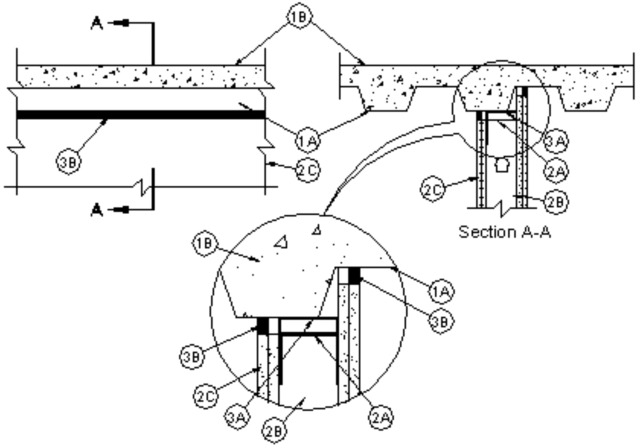
1.Floor Assembly — The fire-rated fluted steel deck/concrete floor assembly shall be constructed of the materials and in the manner described in the individual Floor-Ceiling Design in the UL Fire Resistance Directory and shall include the following construction features:
A.Steel Floor and Form Units* — Max 3 in. (76 mm) deep galv steel fluted floor units having a min valley width of 4-3/4 in. (121 mm).B.Concrete — Min 2-1/2 in. (64 mm) thick reinforced concrete, as measured from the top plane of the floor units.
1A.Roof Assembly — (Not Shown) — As an alternate to the floor assembly (Item 1), a fire rated fluted steel deck roof assembly may be used. The roof assembly shall be constructed of the materials and in the manner described in the individual P900 Series Roof-Ceiling Design in the UL Fire Resistance Directory. The hourly fire rating of the roof assembly shall be equal to or greater than the hourly fire rating of the wall assembly. The roof assembly shall include the following construction features:
A.Steel Roof Deck — Max 3 in. (76 mm) deep galv steel fluted roof deck having a min valley width of 4-3/4 in. (121 mm).B.Roof Insulation — Min 2-1/4 in. (57 mm) thick poured insulating concrete, as measured from the top plane of the steel roof deck.C.Roof Covering* — Hot mopped or cold-application materials compatible with insulating concrete.
2.Wall Assembly — The 1 or 2 hr fire-rated gypsum board/stud wall assembly shall be constructed of the materials and in the manner described in the individual U400 or V400 Series Wall and Partition Design in the UL Fire Resistance Directory and shall include the following construction features:
A.Steel Floor and Ceiling Runners — Floor and ceiling runners of wall assembly shall consist of galv steel channels sized to accommodate steel studs . Ceiling runner to be provided with min 1-1/4 in. (32 mm) to max 3 in. (76 mm) flanges. When deflection channel (Item 3A) is used, flange height of ceiling runner is to be equal to or greater than flange height of deflection channel and the ceiling runner is to nest within the deflection channel with a 1/2 to 1 in. (13 to 25 mm) gap maintained between the top of the ceiling runner and the top of the deflection channel. When deflection channel is not used, ceiling runner installed parallel with direction of fluted steel floor units or roof deck and secured to valley with steel fasteners or welds spaced max 24 in. (610 mm) OC. Ceiling runner not to cantilever more than 1-1/2 in. (38 mm) beyond edge of valley.B.Studs — Steel studs to be min 3-5/8 in. (92 mm) wide. Studs cut 1/2 to 3/4 in. (13 to 19 mm) less in length than assembly height with bottom nesting in and secured to floor runner. When deflection channel (Item 3A) is used, steel studs attached to ceiling runner (Item 2A) with sheet metal screws located 3/4 in. (19 mm) below the bottom to the deflection channel. When deflection channel is not used, studs to nest in ceiling runner without attachment.C.Gypsum Board* — Gypsum board sheets installed to a min total 5/8 or 1-1/4 in. (16 or 32 mm) thickness on each side of wall for 1 and 2 hr rated assemblies, respectively. Wall to be constructed as specified in the individual U400 or V400 Series Design in the UL Fire Resistance Directory, except that a max 1 in. (25 mm) gap shall be maintained between the top of the gypsum board and the underside of the steel floor or roof deck . The screws attaching the gypsum board to the studs along the top of the wall shall be located 1 in. (25 mm) below the bottom of the ceiling runner. No gypsum board attachment screws shall be driven into the ceiling runner or into the optional deflection channel.The hourly fire rating of the joint system is equal to the hourly fire rating of the wall.
3.Joint System — Max separation between floor or roof deck and top of gypsum board (at time of installation of joint system) is 1 in. (25 mm). The joint system is designed to accommodate a max 25 percent compression from it's installed width. The joint system shall consist of forming and fill materials, with or without a deflection channel (Item 3A), as follows:
A.Deflection Channel — Max 3 in. (76 mm) deep min 24 gauge galv steel channel sized to accommodate ceiling runner (Item 2A). Deflection channel installed parallel with direction of fluted steel floor units or roof deck and secured to valley with steel fasteners or welds spaced max 24 in. (610 mm) OC. Deflection channel not to cantilever more than 1-1/2 in. (38 mm) beyond edge of valley. The ceiling runner (Item 2A) is installed within the deflection channel to maintain a 1/2 to 1 in. (13 to 25 mm) gap between the top of the ceiling runner and the top of the deflection channel. The ceiling runner nests inside the deflection channel without attachment.B.Fill, Void or Cavity Material* - Sealant — Min 5/8 in. (16 mm) thickness of fill material installed on each side of the wall between the top of the wall and bottom of floor unit or roof deck, flush with both sides of the wall.
RECTORSEAL — FS 900+ Sealant, Metacaulk MC 150+, or Biostop BF 150+.