HW-D-0444
March 29, 2006
March 29, 2006
Assembly Ratings — 1 and 2 Hr (See Item 2)
Nominal Joint Width — 2 in.
Class II Movement Capabilities — 33% Compression Only
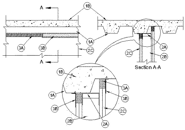
1.Floor Assembly — The fire-rated fluted steel deck/concrete floor assembly shall be constructed of the materials and in the manner described in the individual D900 Series Floor-Ceiling Design in the UL Fire Resistance Directory. The hourly fire rating of the floor assembly shall be equal to or greater than the hourly fire rating of the wall assembly. The floor assembly shall include the following construction features:
A.Steel Floor And Form Units* — Max 3 in. (76 mm) deep galv steel fluted floor units.B.Concrete — Min 2-1/2 in. (64 mm) thick reinforced concrete, as measured from the top plane of the floor units.
2.Wall Assembly — The 1 or 2 hr fire rated gypsum board/steel stud wall assembly shall be constructed of the materials and in the manner described in the individual U400 or V400 Series Wall and Partition Design in the UL Fire Resistance Directory and shall include the following construction features:
A.Steel Floor And Ceiling Runners — Floor and ceiling runners of wall assembly shall consist of galv steel channels sized to accommodate steel studs (Item 2B). Ceiling runner to be provided with min 2-1/2 in. (64 mm) flanges. Ceiling runner installed parallel to direction of fluted steel deck and secured to valley of steel deck with welds or steel masonry anchors spaced a max 12 in. (305 mm) OC.B.Studs — Steel studs to be min 3-1/2 in. (89 mm) wide. Studs cut 1 to 1-1/2 in. (25 to 38 mm) less in length than assembly height. Studs shall be installed with bottom nesting in and resting on floor runner and with top nesting in ceiling runner. Studs secured to floor runner with sheet metal screws. Stud spacing not to exceed 24 in. (610 mm) OC.C.Gypsum Board* — Gypsum board sheets installed to a min total thickness of 5/8 in. (16 mm) or 1-1/4 in. (32 mm) on each side of wall for 1 or 2 hr fire rated assemblies, respectively. Wall to be constructed as specified in the individual Wall and Partition Design in the UL Fire Resistance Directory, except that a nom 2 in. (51 mm) gap shall be maintained between the top of the gypsum board and the bottom of the steel deck and the top row of screws shall be installed into the studs 1 to 1-1/2 in. (25 to 38 mm) below the bottom edge of the ceiling runner flange.The hourly assembly rating of the joint system is equal to the hourly fire rating of the wall.
3.Joint System — Max separation between bottom of steel deck and top of wall at time of installation of joint system is 2 in. ()51 mm). The joint system is designed to accommodate a max of 33 percent compression from its installed width. The joint system consists of forming material and a fill material, as follows:
A.Forming Material* — Min 8 pcf (128 kg/m3) mineral wool batt insulation shall be cut into strips to fill the gap between the top of the gypsum board and bottom of the steel floor units. The width of the strips shall be equal to the total thickness of the gypsum board. The strips of mineral wool are tightly friction-fitted into the gap between the top of the gypsum board and bottom of the steel deck flush with wall surfaces.
ROCK WOOL MANUFACTURING CO — Delta-8AB.Fill, Void or Cavity Material* — Min 1/8 in. (3.2 mm) wet thickness (min 1/16 in. or 1.6 mm dry thickness) of fill material sprayed or troweled on each side of the wall to completely cover mineral wool forming material and to overlap a min of 1/2 in. (13 mm) onto gypsum board and steel deck on both sides of wall.
RECTORSEAL — Metacaulk 1200 Spray, Metacaulk 1200 Caulk Grade