HW-D-0391
October 19, 2015
October 19, 2015
Assembly Rating — 2 Hr
Nominal Joint Width - 1 In.
Class II Movement Capabilities - 12.5% Compression or Extension
L Rating At Ambient - Less Than 1 CFM/Lin Ft
L Rating At 400 F - Less Than 1 CFM/Lin Ft
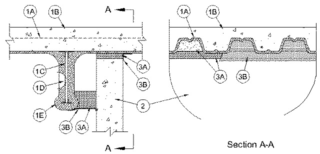
1.Floor Assembly — The fire-rated fluted steel deck/concrete floor assembly shall be constructed of the materials and in the manner described in the individual D700 or D900 Series Floor-Ceiling Design in the UL Fire Resistance Directory. The hourly fire rating of the floor assembly shall be equal to or greater than the hourly fire rating of the wall assembly. The floor assembly shall include the following construction features:
A.Steel Floor and Floor Units* — Max 3 in. (76 mm) deep galv steel fluted floor units.B.Concrete — Min 2-1/2 in. (64 mm) thick reinforced concrete, as measured from the top plane of the floor units.C.Structural Steel Support — Steel beam or open-web steel joist, as specified in the individual D700 or D900 Series Floor-Ceiling Design, used to support steel floor units. Structural steel support oriented parallel to and min 2 in. (51 mm) to max 6 in. (152 mm) from wall assembly.D.Steel Lath — When structural steel support (Item 1C) consists of open-web steel joists, 3/8 in. (10 mm) diamond mesh expanded steel lath having a nom weight of 1.7 to 3.4 lb per sq yd (0.9 to 1.8 kg/m2) shall be installed to completely cover one side of each joist which is located within 6 in. (152 mm) of wall assembly. The lath shall be secured with steel tie wire and shall be fully covered with spray applied fire resistive material.E.Spray-Applied Fire Resistive Material* — Steel floor units and structural steel supports to be sprayed with the thickness of material specified in the individual D700 or D900 Series Design. The flutes of the steel floor units above the structural steel supports shall be filled with spray-applied fire resistive material. The spray-applied fire resistive material in the flutes above the wall shall be applied to follow the contour of the steel floor units.
ISOLATEK INTERNATIONAL — Type 300
GCP APPLIED TECHNOLOGIES INC — Type MK-6/HY, MK-6/HY ES, MK-6s, RG
1A.Roof Assembly — (Not Shown) — As an alternate to the floor assembly (Item 1), a fire rated fluted steel deck roof assembly may be used. The roof assembly shall be constructed of the materials and in the manner described in the individual P700 or P900 Series Roof-Ceiling Design in the UL Fire Resistance Directory. The hourly fire rating of the roof assembly shall be equal to or greater than the hourly fire rating of the wall assembly. The roof assembly shall include the following construction features:
A.Steel Roof Deck — Max 3 in. (76 mm) deep galv steel fluted roof deck.B.Roof Insulation — For P700 Series Designs, min 3/4 in. (19 mm) thick Mineral and Fiber Board* insulation applied in one or more layers directly over steel roof deck or over gypsum board sheathing laid atop steel roof deck as specified in the individual design. For P900 Series Designs, min 2-1/4 in. thick poured insulating concrete, as measured from the top plane of the roof deck as specified in the individual design.C.Roof Covering* — Hot-mopped or cold-application materials compatible with mineral and fiber board insulation.D.Structural Steel Support — Steel beam or open-web steel joist, as specified in the individual P700 or P900 Series Roof-Ceiling Design, used to support steel floor units. Structural steel support oriented parallel to and min 2 in. (51 mm) to max 6 in. (152 mm) from wall assembly.E.Steel Lath — When structural steel support (Item 1D) consists of open-web steel joists, 3/8 in. (10 mm) diamond mesh expanded steel lath having a nom weight of 1.7 to 3.4 lb per sq yd (0.9 to 1.8 kg/m2) shall be installed to completely cover one side of each joist which is located within 6 in. (152 mm) of wall assembly. The lath shall be secured with steel tie wire and shall be fully covered with spray applied fire resistive material.F.Spray-Applied Fire Resistive Material* — Steel roof deck and structural steel supports to be sprayed with a thickness of spray applied fire resistive material as specified in the individual P700 Series Roof-Ceiling design. The flutes of the steel deck above the structural steel supports shall be filled with spray-applied fire resistive material. The spray-applied fire resistive material in the flutes above the wall shall be applied to follow the contour of the steel roof deck.
ISOLATEK INTERNATIONAL — Type 300
GCP APPLIED TECHNOLOGIES INC — Type MK-6/HY, MK-6/HY ES, MK-6s, RG
2.Wall Assembly — Min 6 in. (152 mm) thick steel-reinforced lightweight or normal weight (100-150 pcf or 1600-2400 kg/m3) structural concrete. Wall may also be constructed of any UL Classified Concrete Blocks*.
See Concrete Blocks (CAZT) category in the Fire Resistance Directory for names of manufacturers.
3.Joint System — Max separation between bottom plane of steel deck or spray-applied fire resistive material on the steel deck and the top of the concrete or concrete block wall (at time of installation of joint system) is 1 in. (25 mm). Separation distance between spray applied fire resistive material on structural support member and surface of wall is min 1 in. (25 mm) to max 4 in. (102 mm). The joint system is designed to accommodate a max 12.5 percent compression or extension from its installed width as measured between the bottom plane of the steel deck or the spray-applied fire resistive material on the steel deck and the top of the concrete or concrete block wall. The joint system shall consist of forming and fill materials, as follows:
A.Forming Material* — Nom 4 pcf (64 kg/m3) density mineral wool batt insulation. Sections of mineral wool batt cut to a width of 4 in. (102 mm) and stacked to attain a thickness which is 50 percent greater than the width of the linear gap between the spray applied fire resistive material on the structural steel member and the surface of the wall assembly. Stacked sections of mineral wool compressed 33 percent in thickness and installed cut edge first into linear gap until the bottom edge is flush with the bottom surface of the spray applied fire resistive material on the structural steel member. On the opposite side of the wall, sections of mineral wool batt insulation cut to the width of the wall inserted edge-first between the top of the wall and the steel deck or the spray-applied fire resistive material on the valleys of the steel deck, compressed approx 50 percent in thickness beneath each valley and flush with the wall surface. Additional pieces of mineral wool batt cut to the shape of the steel deck flute, stacked to a min 6 in. (152 mm) thickness and installed in the flutes above the wall flush with the wall surface.
INDUSTRIAL INSULATION GROUP L L C — MinWool-1200 Safing
JOHNS MANVILLE — Safing
ROCK WOOL MANUFACTURING CO — Delta Safing Board
ROCKWOOL MALAYSIA SDN BHD — SAFE
ROCKWOOL — SAFE
THERMAFIBER INC — SAFA1.Forming Material* - Plugs — (Not Shown) — As an alternate to the forming material (Item 3A), mineral wool plugs preformed to the shape of the fluted floor units, may be used within the flutes. Plugs shall be friction fit to completely fill the flutes above the ceiling channel. The plugs shall project beyond each side of the ceiling runner, flush with wall surfaces. Additional forming material, described in Item 3A, to be used in conjunction with the plugs to fill the gap between the top of gypsum board and bottom of steel floor units or roof deck.
ROCK WOOL MANUFACTURING CO — Delta Deck PlugsB.Fill, Void or Cavity Material* — Sealant — Min 1/8 in. (3.2 mm) wet thickness or 1/16 in. (1.6 mm) dry thickness of fill material spray or brush applied over the forming material on each side of the wall. Fill material to overlap a min of 1/2 in. (13 mm) onto the steel deck or the spray-applied fire resistive material on the steel deck and on the spray-applied fire resistive material on the structural steel support member on each side of the wall.
RECTORSEAL — FlameSafe FS3000, Metacaulk 1200, 1500 or Biostop 750, 800 Spray