October 16, 2015
Assembly Ratings — 2 and 3 Hr (See Item 3A)
Nominal Joint Width — 1 and 2 In. (See Item 3)
Class II Movement Capabilities — 25% Compression or Extension
L Rating At Ambient - Less Than 1 CFM/Lin Ft
L Rating At 400 F - Less Than 1 CFM/Lin Ft
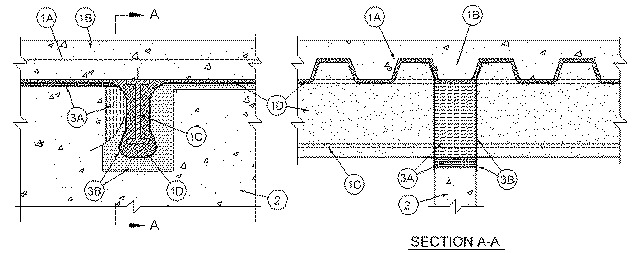
1.Floor Assembly — The fire-rated fluted steel deck/concrete floor assembly shall be constructed of the materials and in the manner described in the individual D700 Series Floor-Ceiling Design in the UL Fire Resistance Directory and shall include the following construction features:
A.Steel Floor and Floor Units* — Max 3 in. (76 mm) deep galv steel fluted floor units.B.Concrete — Min 2-1/2 in. (64 mm) thick reinforced concrete, as measured from the top plane of the steel floor units.C.Structural Steel Support — (Optional) - Steel beam or open-web steel joist, as specified in the individual D700 or D900 Series Floor-Ceiling Design, used to support steel floor units. Structural steel support oriented perpendicular to wall assembly. Where open-web steel joists pass through the fire rated wall, 3/8 in. (10 mm) diamond mesh expanded steel lath having a nom weight of 1.7 to 3.4 lb per sq yd (0.9-1.8 kg/m2) shall be secured to one side of each joist with steel tie wire and the lath shall be fully covered with spray-applied fire resistive material with no min thickness requirement.D.Spray-Applied Fire Resistive Material* — Prior to the installation of the Forming Material and Fill, Void or Cavity Material (Items 3A and 3B, respectively), steel floor units and structural steel supports to be sprayed in accordance with the specifications in the individual D700 Series Design. For D900 Series Designs structural steel supports only to be sprayed in accordance with the specifications in the individual D900 Series Design.
ISOLATEK INTERNATIONAL — Type 300
GCP APPLIED TECHNOLOGIES INC — Type MK-6/HY, MK-6/HY ES, MK-6S and RGThe hourly fire rating of the floor assembly shall be equal to or greater than the hourly rating of the wall assembly.
1A.Roof Assembly (Not Shown) — As an alternate to the floor assembly, a fire-rated fluted steel deck roof assembly may be used. The roof assembly shall be constructed of the materials and in the manner described in the individual P700 and P900 Series Roof-Ceiling Design in the UL Fire Resistance Directory. The hourly rating of the roof assembly shall be equal to or greater than the hourly rating of the wall assembly. The roof assembly shall include the following construction details:
A.Steel Roof Deck — Max 2 in. (51 mm) deep galv steel fluted roof deck.B.Roof Insulation — For P900 Series Designs, min 2-1/4 in. (57 mm) thick poured insulating concrete, as measured from the top plane of the roof deck. For P700 Series Designs, as specified in the individual P700 Series Design.C.Spray-Applied Fire Resistive Materials* — Prior to the installation of the Forming Material and Fill, Void or Cavity Material (Items 3A and 3B, respectively), the steel roof deck shall be sprayed with the thickness of material specified in the individual P700 Series Design. For P900 Series Designs, structural steel supports only to be sprayed in accordance with the specifications in the individual P900 Series Design.
ISOLATEK INTERNATIONAL — Type 300
GCP APPLIED TECHNOLOGIES INC — Type MK-6/HY, MK-6/HY ES, MK-6S and RGThe hourly fire rating of the roof assembly shall be equal to or greater than the hourly rating of the wall assembly.
2.Wall Assembly — Min 6 in. (152 mm) thick reinforced light or normal weight (100-150 or 1600-2400 kg/m3) structural concrete. Wall may also be constructed of any UL Classified Concrete Blocks*. The wall shall consist of a preformed or saw cut opening to accommodate each structural steel support member. A min clearance of 1 in. (25 mm) to a max clearance of 3 in. (76 mm) shall be maintained between the opening and the spray applied fire resistive material on the two sides of the structural support member. The clearance between the opening and the spray applied fire resistive material on the bottom of the structural steel support member shall be max 1 in. (25 mm). For D900 and P900 Series Designs, max separation between bottom of the steel floor units or roof deck and top of concrete wall (at time of installation of joint system) is 2 in. (51 mm). For D700 and P700 Series Designs, max separation between bottom of the spray applied fire resistive material on the steel floor units or roof deck and top of concrete (at time of installation of joint system) is 1 in. (25 mm).
See Concrete Blocks (CAZT) category in the Fire Resistance Directory for names of manufacturers.
The hourly fire rating of the joint system is equal to the hourly fire rating of the wall assembly.
3.Joint System — Max separation between spray applied fire resistive material on bottom of structural support member and opening in top of wall is 1 in. (25 mm). For D900 and P900 Series Designs, max separation between bottom of the steel floor units or roof deck and top of concrete wall (at time of installation of joint system) is 2 in. (51 mm). For D700 and P700 Series Designs, max separation between bottom of the spray applied fire resistive material on the steel floor units or roof deck and top of wall (at time of installation of joint system) is 1 in. (25 mm). The joint system is designed to accommodate a max 25 percent compression or extension from it's installed width as measured between the spray applied fire resistive material on the steel floor units or roof deck and the top of the wall assembly . The joint system shall consist of forming and fill materials, as follows:
A.Forming Material* — Nom 4 pcf (64 kg/m3) mineral wool batt insulation cut to min width of 6 or 6-5/8 in. (152 or 168 mm) for 2 and 3 hr rated assemblies, respectively , and inserted cut edge first into the spaces between the spray-applied fire resistive material on the structural steel member and the opening at the top of the wall, flush with the concrete surface on both sides of the wall. The thickness of forming material shall be sufficient to attain a min compression of 33 percent between the sides of the opening and the protected structural steel member and a min compression of 50 percent between the bottom of the opening and the bottom of the protected structural steel member. Additional sections of mineral wool batt insulation are compressed 50 percent in thickness and are installed cut edge first to completely fill the gap above the top of the concrete, flush with both surfaces of wall.
INDUSTRIAL INSULATION GROUP L L C — MinWool-1200 Safing
JOHNS MANVILLE — Safing
ROCK WOOL MANUFACTURING CO — Delta Safing Board
ROCKWOOL MALAYSIA SDN BHD — SAFE
ROCKWOOL — SAFE
THERMAFIBER INC — SAFB.Fill, Void or Cavity Material* - Sealant — Min 1/8 in. (3.2 mm) wet thickness or 1/16 in. (1.6 mm) dry thickness of fill material sprayed or brushed over the forming material on each side of the wall. Fill material to overlap a min of 1 in. (25 mm) onto the concrete and a min 2 in. (51 mm) onto the spray applied material (Item 1D) on the steel floor unit or roof deck and on the structural steel support member on both sides of wall.
RECTORSEAL — FlameSafe FS3000, Metacaulk 1200, 1500 or Biostop 750, 800 Spray