HW-D-0257
August 25, 2015
August 25, 2015
| ANSI/UL2079 | CAN/ULC S115 |
|---|---|
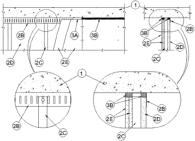
1.Floor Assembly — Min 4-1/2 in. (114 mm) thick reinforced lightweight or normal weight (100-150 pcf or 1600-2400 kg/m3) structural concrete.
2.Shaft Wall Assembly — With the exception of the ceiling runner, the 2 hr fire rated shaft wall assembly shall be constructed of the materials and in the manner described in System B of Design No. U415 in the UL Fire Resistance Directory. The wall shall include the following construction features:
A.Floor Runners — (Not Shown) - "J"-shaped runner, min 2-1/2 in. (64 mm) wide with unequal legs of 1 in. (25 mm) and 2 in. (51 mm) , fabricated from min 24 MSG galv steel. Runners positioned with short leg toward finished side of wall. Runners attached to walls and floor with steel fasteners spaced max 24 in. (610 mm) OC. As an alternate to the "J"-shaped runner, a min 2-1/2 in. (64 mm) wide by 1 or 1-1/4 in. (25 or 32 mm) deep channel formed from min 24 MSG galv steel may be used for the floor runner.B.Light Gauge Framing* — Slotted Ceiling Track Slotted ceiling track shall consist of galv steel channels with slotted flanges. Slotted ceiling track sized to accommodate steel "C-H" studs (Items 2C). Attached to concrete at ceiling with steel fasteners spaced max 12 in. (305 mm) OC.
BRADY CONSTRUCTION INNOVATIONS INC, DBA SLIPTRACK SYSTEMS — SLP-TRK.
MARINO/WARE, DIV OF WARE INDUSTRIES INC — Type SLTC.Steel Studs — "C-H"-shaped steel studs to be min 2-1/2 in. (64 mm) wide and formed of min 24 MSG galv steel. Studs cut 1/2 to 3/4 in. (13 to 19 mm) less in length than assembly height with bottom nesting in and resting on floor runner and with top nesting in slotted ceiling track. Studs spaced 24 in. (610 mm) OC. After installation of gypsum board liner panels (Item 2D), studs secured to flange of floor runner on finished side of wall only with No. 6 by 1/2 in. (13 mm) long self-drilling, self-tapping steel screws. Studs secured to flange of slotted ceiling track on finished side of wall only with No. 8 by 1/2 in. (13 mm) long self-drilling, self-tapping wafer head steel screws at slot mid-height.D.Gypsum Board* — 1 in. (25 mm) thick by 24 in. (610 mm) wide gypsum board liner panels as specified in Design No. U415. Panels cut 1 in. (25 mm) less in length than floor to ceiling height. Vertical edges inserted in "H"-shaped section of "C-H" studs. Free edge of end panels attached to long leg of "J" runner (Item 2A) with 1-5/8 in. (41 mm) long Type S steel screws spaced max 12 in. (305 mm) OC.E.Gypsum Board* — Gypsum board sheets, 1/2 or 5/8 in. (13 or 16 mm) thick, applied vertically or horizontally in two layers on finished side of wall as specified in System B of Design No. U415. A max 1 in. (25 mm) gap shall be maintained between the top of the gypsum board and the bottom surface of the concrete floor. The screws attaching the gypsum board layers to the C-H studs shall be located 1 in. (25 mm) below the bottom of the slotted ceiling track (Item 2C). No gypsum board attachment screws are to penetrate the slotted ceiling track.
3.Joint System — Max separation between bottom of floor and top of liner panel (Item 2D) and between bottom of floor and top of gypsum board sheets (Item 2E) at time of installation of joint system is 3/4 in. (19 mm). The joint system is designed to accommodate a maximum 25 percent compression from its installed width. The joint system consists of bond breaker tape and sealant, as follows:
A.Bond Breaker Tape — Polyethylene tape supplied in rolls. Tape applied to flanges of slotted ceiling track (Item 2D) to prevent bonding of the sealant at points other than the top and bottom of the linear gap. The use of bond breaker tape is dependent upon the type of fill material used within the joint system. If FS 900+, Metacaulk 150+, Metacaulk 1200, Biostop 750 or Biostop BF 150+ caulk is used within the joint system, bond breaker tape is not required. If FS1900, Metacaulk 1000 or Biostop 500+ sealant is used within the joint system, bond breaker tape shall be applied to the ceiling runner (Item 2A) prior to the installation of fill material on both sides of the wall in 1 hr fire rated wall assemblies.B.Fill, Void or Cavity Material* — Sealant Min 1 in. (25 mm) depth of sealant to be installed to fill linear gap between top of gypsum board liner panel (Item 2D) and top inside surface of slotted ceiling track (Item 2B) prior to installation of gypsum board sheets on finished side of wall. Min 1 in. (25 mm) depth of sealant to be installed to fill linear gap between top of gypsum board sheets (Item 2E) and bottom of concrete floor.
RECTORSEAL — FS900+, Metacaulk MC 150+, Biostop BF 150+, FS1900, Metacaulk, 1000, Biostop 500+, Metacaulk 1200 or Biostop 750