
HW-D-0221
June 26, 2023
June 26, 2023
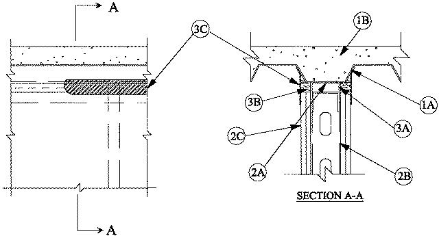
1.Floor Assembly — The fire-rated fluted steel deck/concrete floor assembly shall be constructed of the materials and in the manner described in the individual D900 Series Floor-Ceiling Design in the UL Fire Resistance Directory and shall include the following construction features:A.Steel Floor And Form Units* — Max 3 in. deep galv steel fluted floor units.B.Concrete — Min 2-1/2 in. thick reinforced concrete, as measured from the top plane of the floor units.C.Spray-Applied Fire Resistive Materials* — (Optional)—(Not Shown)—Prior to the installation of the deflection channel, Forming Material and Fill, Void or Cavity Material (Items 3A, 3B, 3C) the steel floor units may be sprayed with a min 5/16 in. to max 1-3/4 in. thickness of fire resistive material.
GCP APPLIED TECHNOLOGIES INC — Type MK-6-HY
2.Wall Assembly — The 1 or 2 hr fire rated gypsum board /steel stud wall assembly shall be constructed of the materials and in the manner described in the individual U400-Series Wall or Partition Design in the UL Fire Resistance Directory and shall include the following construction features:ASteel Floor And Ceiling Runners — Floor and ceiling runners of wall asembly shall consist of galv steel channels sized to accommodate steel studs (Item 2B). Ceiling runner to be provided with 1 in. flanges. Ceiling runner installed within the U-shaped deflection channel (Item 3A) with a 1-1/2 in. gap maintained between the top of ceiling runner and top of deflection plate.A1.Light Gauge Framing*-Slotted Ceiling Runner — When the nom joint width is less than or equal to 1-1/2 in., slotted ceiling runner may be used as an alternate to the ceiling runner in Item 2A. Slotted ceiling runner to consist of galv steel channel with slotted flanges sized to accommodate steel studs (Item 2B). Slotted ceiling runner installed parallel to and centered beneath valleys of fluted steel floor units and secured through spray-applied fire resistive material, if used with steel fasteners spaced max 24 in. OC. When slotted ceiling runner is used, deflection channel (Item 3A) shall not be used.
CEMCO, LLC — CST
BRADY CONSTRUCTION INNOVATIONS INC, DBA SLIPTRACK SYSTEMS — SLP-TRK
MARINO/WARE, DIV OF WARE INDUSTRIES INC — Type SLTB.Studs — Steel studs to be min 3-1/2 in. wide. Studs cut 1/2 to 3/4 in. less in length than assembly height with bottom nesting in and resting on floor runner and with top nesting in ceiling runner without attachment. When slotted ceiling runner (Item 2A1) is used, steel studs secured to slotted ceiling runner with No. 8 by 1/2 in. long wafer head steel screws at midheight of slot on each side of wall. When slotted ceiling runner (Item 2A1) is used, steel studs secured to slotted ceiling runner with No. 8 x 1/2 in. long wafer head steel screws at midheight of slot on each side of wall. When vertical deflection ceiling runner (Item 2A2) is used, steel studs secured to slotted vertical deflection clips, through the bushings, with steel screws at midheight of each slot. Stud spacing not to exceed 24 in. OC .C.Gypsum Board* — Gypsum board installed to a min total thickness of 5/8 in. or 1-1/4 in. on each side of wall for 1 and 2 hr rated assemblies, respectively. Wall to be constructed as specified in the individual Wall and Partition Design in the UL Fire Resistance Directory, except that a nom 2 in. gap shall be maintained between the top of the gypsum board and the bottom of the steel floor units and the top row of screws shall be installed into the studs 4 to 4-1/2 in. below the lower surface of the floor.
3.Joint System — Max separation between bottom of floor or spray-applied fire resistive material, if used, and top of wall at time of installation of joint system is 2 in. The joint system is designed to accommodate a max 20 percent compression or extension from its installed width . The joint system consists of a deflection channel, forming material and a fill material, as follows:A.Deflection Channel — A nom 3-11/16 in. wide by 3 in. deep min No. 22 gauge steel U-shaped channel. Deflection channel installed parallel to and centered beneath valleys of fluted steel floor units and secured through fire resistive material, if used, with steel fasteners or by welds spaced max 12 in. OC. The ceiling runner (Item 2A) is installed within the deflection channel to maintain a 1-1/2 in. gap between the top of the ceiling runner and the top of the deflection channel. The ceiling runner is not fastened to the deflection channel.B.Forming Material* — Nom 5/8 in. and 1-1/4 in. thickness of min 4 pcf mineral wool batt insulation, for 1 and 2 hr rated asemblies respectively, cut into strips and compressed 33 percent in width and firmly packed into the gap between the top of the gypsum board and bottom of the steel floor units on spray-applied fire resistive material, if used, flush with both surfaces of the wall.
INDUSTRIAL INSULATION GROUP L L C — MinWool-1200 Safing
JOHNS MANVILLE — Safing
ROCK WOOL MANUFACTURING CO — Delta Safing Board
ROCKWOOL MALAYSIA SDN BHD — SAFE
ROCKWOOL — SAFE
THERMAFIBER INC — SAFC.Fill, Void or Cavity Material* — Min 1/8 in. wet thickness of fill material sprayed or troweled on each side of the wall to completely cover mineral wool forming material and to overlap a min of 1/2 in. onto gypsum board and steel deck on both sides of wall. When spray-applied fire resistive material* is applied to the steel floor and form units*, the fill material is to overlap the gypsum board a min of 1/2 in. and the spray-applied fire resistive material a min of 2 in. on both sides of wall.
RECTORSEAL — Biostop 750 Spray, Biostop 750 Caulk Grade
Preparing PDF…