HW-D-0220
July 4, 2025
July 4, 2025
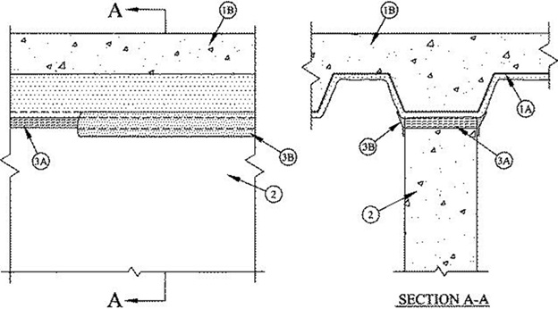
1.Floor Assembly — The fire-rated fluted steel deck/concrete floor assembly shall be constructed of the materials and in the manner described in the individual D700 Series Floor-Ceiling Design in the UL Fire Resistance Directory and shall include the following construction features:A.Steel Floor and Floor Units* — Max 3 in. (76 mm) deep galv steel fluted floor units.B.Concrete — Min 2-1/2 in. (64 mm) thick reinforced lightweight or normal weight (100-150 pcf or 1600-2400 kg/m3) concrete, as measured from the top plane of the floor units.C.Spray-Applied Fire Resistive Material* — Prior to the installation of the Forming Material and Fill, Void or Cavity Materials (Items 3A and 3B), all surfaces of the steel floor units to be sprayed with the thickness of material specified in the individual D700 Series Design.
GCP APPLIED TECHNOLOGIES INC — Type MK-6/HY, MK-6/HY ES, RG and MK-6S.
1A.Roof Assembly (Not Shown) — As an alternate to the floor assembly, a fire-rated fluted steel deck roof assembly may be used. The roof assembly shall be constructed of the materials and in the manner described in the individual P700 Series Roof-Ceiling Design in the UL Fire Resistance Directory. The hourly rating of the roof assembly shall be equal to or greater than the hourly rating of the wall assembly. The roof assembly shall include the following construction details:A.Steel Roof Deck — Max 3 in. (76 mm) deep galv steel fluted roof deck.B.Roof Insulation — As specified in the individual P700 Series Design.C.Spray — Applied Fire Resistive Materials* — Prior to the installation of the Forming Material and Fill, Void or Cavity Materials (Items 3A and 3B, respectively), the steel roof deck shall be sprayed with the thickness of material specified in the individual P700 Series Design.
GCP APPLIED TECHNOLOGIES INC — Types MK-6/HY, MK-6/HY ES, RG and MK-6S.
2.Wall Assembly — Min 6 in. (152 mm) thick reinforced lightweight or normal weight (100 - 150 pcf or 1600-2400 kg/m3) structural concrete. Wall may also be constructed of any UL Classified Concrete Blocks*. Wall shall be installed parallel to and centered under the valleys of the flutes of the steel floor or roof deck.See Concrete Blocks (CAZT) category in the Fire Resistance Directory for names of manufacturers.
3.Joint System — Max separation between bottom of spray-applied steel fire resistive material and top of wall (at time of installation of joint system) is 1 in. The joint system is designed to accommodate a max 25 percent compression or extension from it's installed width. The joint system shall consist of a forming material and fill material, as follows:A.Forming Material* — Min 4 pcf (64 kg/m3) mineral wool batt insulation cut into strips with a width equal to the overall thickness of the wall. Strips compressed 50 percent in thickness and inserted into the gap between the top of the wall and the bottom of the spray-applied fire resistive material. Forming material to be installed flush with both surfaces of the wall.
INDUSTRIAL INSULATION GROUP L L C — MinWool-1200 Safing
ROCK WOOL MANUFACTURING CO — Delta Safing Board
ROCKWOOL MALAYSIA SDN BHD — SAFE
ROCKWOOL — SAFE Mineral Wool
THERMAFIBER/OWENS CORNING — SAFB.Fill, Void or Cavity Material* — Spray — Min 1/8 in. (3.2 mm) wet thickness of fill material spray or brush applied on each side of the wall to completely cover the mineral wool forming material and to overlap a min 1/2 in. (13 mm) onto concrete wall and the spray-applied fire resistive material on both sides of wall.
RECTORSEAL — FlameSafe FS3000, Metacaulk 1200, 1500 or Biostop 750, 800 Spray