HW-D-0215
May 14, 2014
May 14, 2014
| ANSI/UL2079 | CAN/ULC S115 |
|---|---|
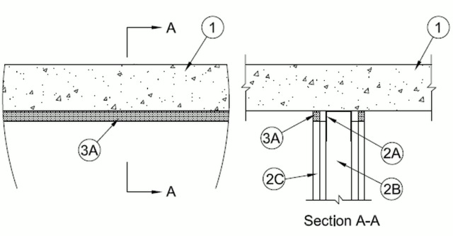
1.Floor Assembly — Min 4-1/2 in. (114 mm) thick reinforced lightweight or normal weight (100-150 pcf or 1600-2400 kg/m3) structural concrete or any UL Classified Concrete Blocks*.See Concrete Blocks (CAZT) category in the Fire Resistance Directory for names of manufacturers.
2.Wall Assembly — The 1 or 2 hr fire rated gypsum board/stud wall assembly shall be constructed of the materials and in the manner specified in the individual U400, V400 or W400 Series Wall and Partition Designs in the UL Fire Resistance Directory and shall include the following construction features:
A.Steel Floor And Ceiling Runners — Floor and ceiling runners of wall assembly shall consist of galv steel channels sized to accommodate steel studs (Item 2B). Ceiling runner to be provided with min 1-1/4 in. (32 mm) flanges. Ceiling runner shall be secured to floor with steel fasteners spaced max 24 in. (610 mm) OC.B.Studs — Steel studs to be min 3-1/2 in. (89 mm) wide. Studs cut 1/2 to 3/4 in. (13 to 19 mm) less in length than assembly height with bottom nesting in and resting on floor runner and with top nesting in ceiling runner. Studs secured only to floor runner with sheet metal screw. Stud spacing not to exceed 24 in. (610 mm) OC.C.Gypsum Board* — Gypsum board sheets installed to a min total thickness of 5/8 in. (16 mm) or 1-1/4 in. (32 mm) on each side of wall, for 1 and 2 hr rated wall assemblies, respectively. Wall to be constructed as specified in the individual Wall and Partition Design in the UL Fire Resistance Directory, except that a nom 3/4 in. (19 mm) gap shall be maintained between the top of the gypsum board and the bottom of the floor and the top row of screws shall be installed into the studs 2 in. (51 mm) below the lower surface the floor.The hourly assembly ratings of the joint system are equal to the fire rating of the wall.
3.Joint System — Max separation between bottom of floor and top of wall at time of installation of joint system is 3/4 in. (19 mm). The joint system is designed to accommodate a max 20 percent compression or extension from its installed width or max 33 percent compression only from its installed width. The joint system consists of a fill material, as follows:
A.Fill, Void or Cavity Material* - Caulk — Min 5/8 in. (16 mm) thickness of fill material applied within the joint, flush with both surfaces of wall.
RECTORSEAL — MC 150+, Metacaulk 1200 Caulk