HW-D-0144
June 26, 2023
June 26, 2023
| ANSI/UL2079 | CAN/ULC S115 |
|---|---|
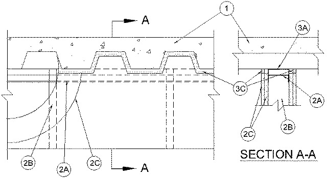
1.Floor Assembly — The fire-rated fluted steel deck/concrete floor assembly shall be constructed of the materials and in the manner described in the individual Floor-Ceiling Design in the UL Fire Resistance Directory and shall include the following construction features:A.Steel Floor And Floor Units* — Max 3 in. (76 mm) deep galv steel fluted floor units.B.Concrete — Min 2-1/2 in. (64 mm) thick reinforced concrete, as measured from the top plane of the floor units.
1A.Roof Assembly — (Not Shown) — As an alternate to the floor assembly, a fire-rated fluted steel deck roof assembly may be used. The roof assembly shall be constructed of the materials and in the manner described in the individual P900 Series Roof-Ceiling Design in the UL Fire Resistance Directory. The hourly rating of the roof assembly shall be equal to or greater than the hourly rating of the wall assembly. The roof assembly shall include the following construction features:A.Steel Roof Deck — Max 3 in. (76 mm) deep galv steel fluted roof deck.B.Roof Insulation — Min 2-1/4 in. (57 mm) thick poured insulating concrete, as measured from the top plane of the roof deck.
2.Wall Assembly — The 1 or 2 hr fire-rated gypsum board/steel stud wall assembly shall be constructed of the materials and in the manner described in the individual U400 or V400 Series Wall and Partition Design in the UL Fire Resistance Directory and shall include the following construction features:A.Steel Floor and Ceiling Runners — Floor and ceiling runners of wall assembly shall consist of min No. 25 gauge galv steel channels sized to accommodate steel studs (Item 2B). Ceiling runner to be provided with 3 in. (76 mm) flanges. When U shaped deflection channel (Item 3A) is used, ceiling runner is installed within the U-shaped deflection channel with 1 in. (25 mm) gap maintained between the top of ceiling runner and top of deflection channel. When deflection channel is not used, ceiling runner installed perpendicular to the direction of the fluted steel deck and secured to valleys with steel masonry anchors or weld spaced a max 12 in. (305 mm) 0C.A1.Light Gauge Framing* —Slotted Ceiling Runner — Slotted ceiling runner may be used as an alternate to the ceiling runner in Item 2A. Slotted ceiling runner to consist of galv steel channel with slotted flanges sized to accommodate steel studs (Item 2B). Slotted ceiling runner installed perpendicular to direction of fluted steel floor deck and secured to valleys with steel masonry anchors spaced max 12 in. (305 mm) OC. When slotted ceiling runner is used, deflection channel (Item 3A) shall not be used.
SCAFCO STEEL STUD MANUFACTURING CO
BRADY CONSTRUCTION INNOVATIONS INC, DBA SLIPTRACK SYSTEMS — SLP-TRK
CEMCO, LLC — CST
MARINO/WARE, DIV OF WARE INDUSTRIES INC — Type SLT
TELLING INDUSTRIES L L C — True-Action Deflection TrackA2.Light Gauge Framing* —Vertical Deflection Clip* — (Optional) Steel clips can be used in conjunction with steel studs (Item 2B), ceiling runner (Item 2A) or deflection channel (Item 3A). Clips installed over the top of studs and inserted within the ceiling runner or deflection channel. Clip shall be secured to the ceiling runner or deflection channel with No. 8 self drilling, self tapping steel fasteners through holes provided within the clip. Clip may be secured to the stud with No. 6 pan head steel screw through holes provided within the clip. As an alternate, the legs of the clip may be installed over the top of the stud without attachment in accordance with manufacturer's installation instructions.
FLEX-ABILITY CONCEPTS L L C — Three Legged Dog Deflection ClipA3.Light Gauge Framing*- Notched Ceiling Runner — As an alternate to the ceiling runners in Items 2A through 2A3, notched ceiling runners to consist of C-shaped galv steel channel with notched return flanges sized to accommodate steel studs (Item 2B). Notched ceiling runner installed perpendicular to direction of fluted steel floor deck and secured to valleys with steel masonry anchors spaced max 24 in. (610 mm) OC. When notched ceiling runner is used, deflection channel (Item 3A) shall not be used.
OLMAR SUPPLY INC — Type SCRB.Studs — Steel studs to be min 3-5/8 in. (92 mm) wide. Studs cut 3/4 in. (19 mm) less in length than assembly height with bottom nesting in and secured to floor runner. When deflection channel (Item 3A) is used, steel studs attached to ceiling runner (Item 2A) with sheet metal screws located 1/2 in. (13 mm) below bottom of deflection channel. When deflection channel is not used, studs to nest in ceiling runners without attachment. When slotted ceiling runner (Item 2A1) is used, steel studs secured to slotted ceiling runner with No. 8 by 1/2 in. (13 mm) long wafer head steel screws at midheight of slot on each side of wall. Stud spacing not to exceed 24 in. (610 mm) OC.C.Gypsum Board* — Gypsum board sheets installed to a min total 5/8 or 1-1/4 in. (16 or 32 mm) thickness on each side of wall for a 1 or 2 hr fire-rated wall, respectively. Wall to be constructed as specified in the individual Wall and Partition Design in the UL Fire Resistance Directory, except that the gypsum board is cut to fit the contour of the steel floor units with a nom 1 in. (25 mm) gap. In addition, the top row of screws shall be installed 1/2 to 1 in. (13 to 25 mm) below the bottom edge of the ceiling runner flange.The hourly ratings of the joint system are equal to the hourly fire rating of the wall.
3.Joint System — Max separation between bottom of floor and top of wall (at time of installation of joint system) is 1 in. (25 mm). The joint system is designed to accommodate a max 25 percent compression from it's installed width. The joint system shall consist of a material with or without a deflection channel as follows:A.Deflection Channel — (Optional) — Nom 3 in. (76 mm) deep by min 25 gauge galv steel U-shaped channel sized to accommodate ceiling runner(Item 2A). Deflection channel installed perpendicular to direction of fluted steel deck and secured to valleys with steel masonry anchors or by welds spaced max 12 in. (305 mm) OC. The ceiling runner is installed within the deflection channel to maintain a 1 in. (25 mm) gap between the top of the ceiling runner and the top of the deflection channel. The ceiling runner is not fastened to the deflection channel.B.Packing Material — (Not Shown) — Optional in 2 hr fire rated assemblies, foam backer rod friction fitted into joint opening and recessed to accommodate the required thickness of fill material.C.Fill, Void or Cavity Material* — Sealant — Min 5/8 in. (16 mm) thickness of fill material applied on each side of wall between the top of the gypsum board and all surfaces of the steel floor unit, flush with each surface of the wall. The use of bond breaker tape is dependent upon the type of fill material used within the joint system. If 900+ Sealant is used within the joint system, bond breaker tape is not required. If 1900 Sealant is used within the joint system, bond breaker tape shall be applied to the ceiling runner (Item 2A) or deflection channel (Item 3A) prior to the installation of fill material on both sides of the wall in 1 hr fire rated wall assemblies and in 2 hr fire rated wall assemblies where optional backer rod is not used.
RECTORSEAL — FlameSafe FS 900+ FS 1900 Metacaulk 1000, Metacaulk 350i, Metacaulk MC 150+, Biostop 350i, Biostop BF 150+, Biostop 500+