January 12, 2021
| ANSI/UL2079 | CAN/ULC S115 |
|---|---|
1.Floor Assembly — The fire-rated fluted steel deck/concrete floor assembly shall be constructed of the materials and in the manner described in the individual Floor-Ceiling Design in the UL Fire Resistance Directory. The hourly fire rating of the floor assembly shall be equal to or greater than the hourly fire rating of the wall assembly. The floor assembly shall include the following construction features:
A.Steel Floor and Form Units* — Max 3 in. (76 mm) deep galv fluted floor units.B.Concrete — Min 2-1/2 in. (64 mm) thick reinforced lightweight or normal weight (100-150 pcf or 1600-2400 kg/m3) concrete, as measured from the top plane of the floor units.
1A.Roof Assembly — As an alternate to Item 1, the fire-rated roof assembly shall be constructed of the materials and in the manner described in the individual P900 Series Roof-Ceiling Designs in the UL Fire Resistance Directory and shall contain max 3 in. (76 mm) deep galv steel fluted roof units. The hourly fire rating of the roof assembly shall be equal to or greater than the hourly fire rating of the wall assembly. In the case of spray-applied protection materials on the steel roof units, the joint system shall be installed prior to the spray-applied protection material.
1B.Floor Assembly — As an alternate to Item 1, min 4-1/2 in. (114 mm) thick reinforced lightweight or normal weight (100-150 pcf or 1600-2400 kg/m3) structural concrete.
2.Wall Assembly — The 1 or 2 hr fire-rated gypsum board /steel stud wall assembly shall be constructed of the materials and in the manner described in the individual U400 and V400-Series Wall and Partition Design in the UL Fire Resistance Directory and shall include the following construction features:
A.Light Gauge Framing* — Deflection Track — Deflection track of wall assembly shall consist of min No. 25 gauge galv steel channels sized to accommodate steel studs (Item 2C) and with offset legs to accommodate wall cladding (Item 3A). Deflection track installed perpendicular to floor units. Min No. 25 gauge deflection track secured on both sides to valley of floor units with 1-1/2 in. (38 mm) long welds spaced max 12 in. (305 mm) OC. Min No. 20 gauge deflection track may be secured with steel fasteners spaced 12 in. (305 mm) OC.
FIRE TRAK CORP —Shadowline and Cavity Shadowline B.Studs — Steel studs to be min 2-1/2 in. (64 mm) wide and as specified in the individual Wall and Partition Design in the UL Fire Resistance Directory. Studs cut 1-1/2 in. (38 mm) less in length than the assembly height with bottom nesting in and resting on floor runner and with top nesting in ceiling runner without attachment. Stud spacing not to exceed 24 in. (610 mm) OC.C.Gypsum Board* — Gypsum board sheets installed and attached to studs and runners as specified in the individual Wall and Partition Design in the UL Fire Resistance Directory, except that a nominal 1 in. (25 mm) gap shall be maintained between top of the gypsum board and the bottom flange of the deflection track. Top row of screws shall be installed into the studs 3 in. (76 mm) below the top edge of the gypsum board sheets.D.Bracing — (Not shown) — Bracing as specified in the individual Wall and Partition Design in the UL Fire Resistance Directory.The hourly assembly rating of the joint system is equal to the fire rating of the wall.
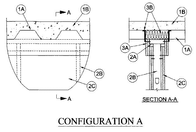
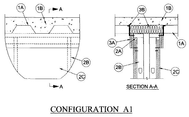
Firestop Configuration A and A1
3.Joint System — Max separation between bottom flange of the deflection track and top of gypsum board (at the time of installation of the joint system) is 1 in. (25 mm). The joint system is designed to accommodate a max 100 percent compression or extension from its installed width. The joint system consists of wall cladding, packing material and a fill material as follows:
A.Wall Cladding — Strips of the gypsum board material attached to the deflection track. The number of layers, board type and thickness and fastener type shall be as specified for the gypsum board in the individual Wall and Partition Design in the UL Fire Resistance Directory. Fasteners shall be max spaced 3 in. (76 mm) OC. The top of the wall cladding shall be flush with the valleys of the steel floor units and overlap the gypsum board 4 in. (102 mm).B.Flute Fill — The batt insulation and fill material are to be installed as specified in the Joint Systems in the table below:
Manufacturer Product Designation System No. 3M Company FireDam Spray 200 HW-D-0020 3M Company 3M Fire and Water Barrier Tape HW-D-0020 A/D Fire Protection Systems Inc. A/D FireBarrier Seal N/S HW-D-0247 Passive Fire Protection Partners 5100SP HW-D-0025 Grabber Construction Products Inc. GrabberGard EFS HW-D-0357 Hilti Construction Chemicals CP 672 Fire Spray or CFS-SP WB Firestop Joint Spray HW-D-0042 Rectorseal Biostop 700 HW-D-0019 Rectorseal Biostop 750 Spray, Biostop 750 Caulk Grade HW-D-0033 or HW-D-0059 Rectorseal Metacaulk 1100 HW-D-0018 Rectorseal Metacaulk 1200 Spray, Metacaulk 1200 Caulk Grade HW-D-0032 or HW-D-0058 Specified Technologies Inc. SpecSeal AS 200 Spray HW-D-0054 Tremco TREMstop Acrylic SP HW-D-0091 Rectorseal FS3000, Metacaulk 1500 or Biostop 800 HW-D-0108
3M COMPANY —Fire Dam Spray 200, 3M Fire and Water Barrier Tape
A/D FIRE PROTECTION SYSTEMS INC —A/D FireBarrier Seal N/S
GRABBER CONSTRUCTION PRODUCTS INC —GrabberGard EFS
PASSIVE FIRE PROTECTION PARTNERS —5100SP
HILTI CONSTRUCTION CHEMICALS, DIV OF HILTI INC —CP 672 Fire Spray or CFS-SP WB Firestop Joint Spray
RECTORSEAL —Metacaulk 1100, Metacaulk 1200 Spray, Metacaulk 1200 Caulk Grade, Biostop 700, Biostop 750 Spray, Biostop 750 Caulk Grade, FlameSafe FS3000, Metacaulk 1200, 1500 or Biostop 750, 800 Spray
SPECIFIED TECHNOLOGIES INC —SpecSeal AS 200 Spray
TREMCO INC —TREMstop Acrylic SP
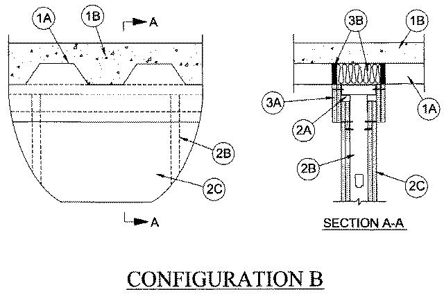
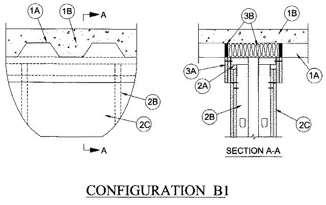
Firestop Configuration B and B1
3.Joint System- — Max separation between bottom flange of the deflection track and top of wallboard (at the time of installation of the joint system) is 1 in. (25 mm). The joint system is designed to accommodate a max 100 percent compression or extension from its installed width. The joint system consists of wall cladding, packing material and a fill material as follows:
A.Wall Cladding — Strips of the gypsum board material attached to the deflection track. The number of layers, board type and thickness and fastener type shall be as specified for the gypsum wallboard in the individual Wall and Partition Design in the UL Fire Resistance Directory. Fasteners shall be max spaced 3 in. (76 mm) OC. The top of the wall cladding shall be flush with the valleys of the steel floor units and overlap the gypsum board 4 in. (102 mm).B.Flute Fill — The batt insulation and fill material are to be installed as specified in the systems in the table below:
Manufacturer Product Designation System No. 3M Company FB 1000NS HW-S-0028 3M Company FB 2000 HW-S-0002 3M Company FB 2000+ HW-S-0002 A/D Fire Protection Systems Inc. A/D FireBarrier Seal N/S HW-D-0247 Hilti Construction Chemicals FS611A HW-D-0003 Hilti Construction Chemicals FS-ONE HW-D-0003 Hilti Construction Chemicals CP601S or CFS-S SIL GG HW-D-0046 Hilti Construction Chemicals CP606 HW-D-0045 Instant Firestop Mfg. 344-GG HW-S-0008 Nuco Inc. Self Seal GG200 HW-S-0011 Rectorseal Metacaulk 835+ HW-S-0023 Rectorseal Metacaulk 1000 HW-D-0014 Rectorseal Biostop 500+ HW-D-0015 Rectorseal Biotherm 1000 HW-S-0022 Specified Technologies Inc. SpecSeal ES HW-D-0034 United States Gypsum Co. RFC HW-S-0001
3M COMPANY —FB 1000NS, FB 2000, FB 2000+
A/D FIRE PROTECTION SYSTEMS INC —A/D FireBarrier Seal N/S
HILTI CONSTRUCTION CHEMICALS, DIV OF HILTI INC —CP601S, CFS-S SIL GG, CP606, FS611A, FS-ONE Sealant or FS-ONE MAX Intumescent Sealant
NUCO INC —Self Seal GG-200
RECTORSEAL —Metacaulk 835+, Metacaulk 1000, Biostop 500+ Caulk, Biotherm 100
SPECIFIED TECHNOLOGIES INC —SpecSeal ES Sealant
UNITED STATES GYPSUM CO —RFC