June 26, 2023
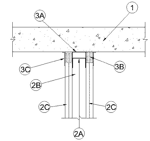
1.Floor Assembly — Min 4-1/2 in. (114 mm) thick steel reinforced lightweight or normal weight (100-150 pcf or 1600-2400 kg/m3) structural concrete. Floor may also be constructed of any min 6 in. (152 mm) thick UL Classified hollow-core Precast Concrete Units* .See Precast Concrete Units (CFTV) category in the Fire Resistance Directory for names of manufacturers.
The hourly fire rating of the floor assembly shall be equal or greater than the hourly fire rating of the wall assembly.
2.Wall Assembly — The 1, 2, 3 or 4 hr fire-rated gypsum board/stud wall assembly shall be constructed of the materials and in the manner described in the individual U400 or V400 Series Wall and Partition Design in the UL Fire Resistance Directory and shall include the following construction features:A.Steel Floor and Ceiling Runners — Floor and ceiling runners of wall assembly shall consist of min No. 25 gauge galv steel channels sized to accommodate steel studs (Item 2B). Ceiling runner to be provided with 3 in. (76 mm) flanges. When U-shaped deflection channel is used, ceiling runner is installed within the U-shaped deflection channel (Item 3B) with 1 in. (25 mm) gap maintained between the top of ceiling runner and top of deflection channel . When deflection channel is not used, ceiling runner is secured to concrete floor slab with steel masonry anchors spaced a max 12 in. (305 mm) OC.A1.Light Gauge Framing* - Slotted Ceiling Runner — When the nom joint width is less than or equal to 1-3/4 in. (44 mm), slotted ceiling runner may be used as an alternate to the ceiling runner in Item 2A. Slotted ceiling runner to consist of galv steel channel with slotted flanges sized to accommodate steel studs (Item 2B). Slotted ceiling runner secured to concrete floor slab with steel masonry anchors spaced max 12 in. (305 mm) OC. When slotted ceiling runner is used, deflection channel (Item 3A) shall not be used.
BRADY CONSTRUCTION INNOVATIONS INC, DBA SLIPTRACK SYSTEMS — SLP-TRK
CEMCO, LLC — CST
CLARKDIETRICH BUILDING SYSTEMS — Type SLT, SLT-H
MARINO/WARE, DIV OF WARE INDUSTRIES INC — Type SLT
METAL-LITE INC — The System
RAM SALES L L C — RAM Slotted Track
SCAFCO STEEL STUD MANUFACTURING CO
TELLING INDUSTRIES L L C — True-Action Deflection TrackA2.Light Gauge Framing* — Vertical Deflection Clip* — (Optional) — Steel clips can be used in conjunction with steel studs (Item 2B), ceiling runner (Item 2A) or deflection channel (Item 3A). Clips installed over the top of studs and inserted within the ceiling runner or deflection channel. Clip shall be secured to the ceiling runner or deflection channel with No. 8 self drilling, self tapping steel fasteners through holes provided within the clip. Clip may be secured to the stud with No. 6 pan head steel screw through holes provided within the clip. As an alternate, the legs of the clip may be installed over the top of the stud without attachment in accordance with manufacturer's installation instructions.
FLEX-ABILITY CONCEPTS L L C — Three Legged Dog Deflection ClipA3.Light Gauge Framing*- Notched Ceiling Runner — As an alternate to the ceiling runners in Items 2A through 2A3, notched ceiling runners to consist of C-shaped galv steel channel with notched return flanges sized to accommodate steel studs (Item 2B). Notched ceiling runner secured to concrete floor slab with steel masonry anchors spaced max 24 in. (610 mm) OC. When notched ceiling runner is used, deflection channel (Item 3A) shall not be used.
OLMAR SUPPLY INC — Type SCRB.Studs — Steel studs to be min 3-5/8 in. (92 mm) wide. Studs cut 3/4 in. (19 mm) less in length than assembly height with bottom nesting in and resting on floor runner and with top nesting in ceiling runner without attachment. When slotted ceiling runner (Item 2A1) is used, steel studs secured to slotted ceiling runner with No. 8 by 1/2 in. (13 mm) long wafer head steel screws at midheight of slot on each side of wall. Stud spacing not to exceed 24 in. (610 mm) OC.C.Gypsum Board* — Gypsum board sheets installed to a min total thickness of 5/8 in., 1-1/4 in., 1-1/2 in. or 2 in. (16, 32, 38 or 51 mm) on each side of wall for 1, 2, 3 and 4 hr fire rated wall assemblies, respectively . Wall to be constructed as specified in the individual U400 Series Design in the UL Fire Resistance Directory, except that a nom 1-1/2 or 2 in. (38 or 51 mm) gap (see Item 3) shall be maintained between the top of the gypsum board and the bottom surface of the floor. The top row of screws shall be installed into the studs 4-3/4 in. (121 mm) below floor.The hourly fire rating of the joint system is equal to the hourly fire rating of the wall.
3.Joint System — The max separation between bottom of floor and top of wall (at time of installation of joint system) is dependent upon the hourly rating of the wall. Max separation between bottom of floor and top of wall (at time of installation of joint system) is 1-1/2 in. (38 mm) for 1 hr fire rated assemblies and 2 in. (51 mm) for 2, 3 and 4 hr fire rated assemblies. The joint system is designed to accommodate a max 25 percent compression or extension from its installed width. The joint system shall consist of an optional deflection channel , and forming and fill materials as follows:A.Deflection Channel — (Optional) - A nom 3-3/4 in. (95 mm) wide by min 3 in. (76 mm) deep min 25 gauge steel U-shaped channel. Deflection channel secured to concrete floor slab with steel masonry anchors spaced max 12 in. (305 mm) OC. The ceiling runner (Item 2A) is installed within the deflection channel to maintain a 1 in. (25 mm) gap between the top of the ceiling runner and the top of the deflection channel. The ceiling runner is not fastened to the deflection channel.B.Forming Material* — Strips of min 4 pcf (64 kg/m3) mineral wool batt insulation cut to a thickness equal to the overall thickness of the gypsum board and compressed 50 percent in thickness and installed cut edge first to fill the gap between the top of the wall and bottom of the floor. The forming material shall be flush with both surfaces of the wall.The type and manufacturer of forming material used within the joint system is dependent upon the hourly rating of the wall assembly as shown in the table below:
Rating of Wall, hr Manufacturer of Mineral Wool Type of Mineral Wool 1, 2, & 3 IIG Minwool MinWool-1200 Safing 1, 2, 3, & 4 Roxul Inc SAFE Mineral Wool 1 & 2 Rock Wool Manufacturing Delta Safing Insulation
INDUSTRIAL INSULATION GROUP L L C — MinWool-1200 Safing
JOHNS MANVILLE — Safing
ROCK WOOL MANUFACTURING CO — Delta Safing Board
ROCKWOOL MALAYSIA SDN BHD — SAFE
ROCKWOOL — SAFE
THERMAFIBER INC — SAFC.Fill, Void or Cavity Material* — Sealant — Min 1/16 in. (1.6 mm) dry thickness (min 1/8 in. or 3.2 mm wet thickness) of fill material spray or brush applied over mineral wool on each side of the wall between the top of the wall and the bottom of the concrete floor and overlapping a min 1/2 in. (13 mm) onto the concrete floor and gypsum board on both sides of wall.
RECTORSEAL — FlameSafe FS3000, Metacaulk 1200, 1500 or Biostop 750, 800 Spray