HW-D-0014
June 13, 2011
June 13, 2011
Assembly Rating — 2 Hr
Joint Width — 3/4 in. Max
Class II and III Movement Capabilities — 25 or 30%
Compression or Extension (See Item 3)
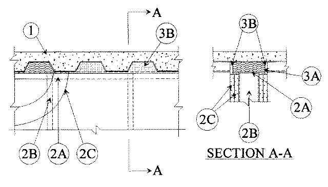
1.Floor Assembly — The fire-rated fluted steel deck/concrete floor assembly shall be constructed of the materials and in the manner described in the individual Floor-Ceiling Design in the UL Fire Resistance Directory and shall include the following construction features:
A.Steel Floor and Form Units* — Max 3 in. deep galv steel fluted floor units.B.Concrete — Min 2-1/2 in. thick reinforced concrete, as measured from the top plane of the floor units.
2.Wall Assembly — The 2 h fire-rated gypsum board/steel stud wall assembly shall be constructed of the materials and in the manner described in the individual U400 Series Wall and Partition Design in the UL Fire Resistance Directory and shall include the following construction features:
A.Steel Floor and Ceiling Runners — Floor and ceiling runners of wall assembly shall consist of min No. 25 gauge galv steel channels sized to accommodate steel studs (Item 2B). Ceiling runner to be provided with 2 in. flanges. Ceiling runner secured to valleys of steel floor units (Item 1A) with steel fasteners or by welds spaced max 12 in. OC.B.Studs — Steel studs to be min 2-1/2 in. wide. Studs cut 5/8 in. less in length than assembly height with bottom nesting in and resting on floor runner and with top nesting in ceiling runner without attachment. Stud spacing not to exceed 24 in. OC.C.Gypsum Board* — Gypsum board sheets installed to a min total thickness of 1-1/4 in. on each side of wall. Wall to be constructed as specified in the individual Wall and Partition Design in the UL Fire Resistance Directory, except that a nom 5/8 to 3/4 in. gap shall be maintained between the top of the gypsum board and the bottom of the steel floor units and the top row of screws shall be installed into the studs 4 in. below the valleys of the steel floor units.
3.Joint System — Max separation between bottom of floor and top of wall (at time of installation of joint system) is 3/4 in. The joint system is designed to accommodate a max 30 percent compression or extension when it is installed to a max width of 5/8 in. or 25 percent compression or extension when it is installed to a max width of 3/4 in . The joint system consists of a packing material and a fill material in the flutes of the steel floor units and between the top of the wallboard and bottom of the steel floor units, as follows.
A.Packing Material — Min 4-1/2 in. thickness of min 0.5 pcf density fiberglass insulation firmly packed into flutes of steel floor units and between top of wall and bottom of the steel floor units, and recessed from each surface of wall to accommodate the required thickness of fill material.B.Fill, Void or Cavity Material* — Min 1/4 in. thickness of fill material installed on each side of the wall in the flutes of the steel floor units and between the top of the wall and the bottom of the steel floor units, flush with each surface of wallboard.
RECTORSEAL — Metacaulk 1000