BW-S-0036
June 21, 2023
June 21, 2023
| ANSI/UL2079 | CAN/ULC S115 |
|---|---|
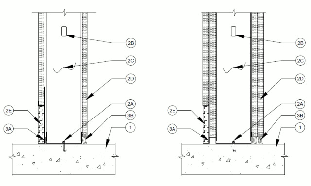
1.Floor Assembly — Min 4-1/2 in. (114 mm) thick reinforced lightweight or normal weight (100-150 pcf or 1600-2400 kg/m3) structural concrete. Floor may also be constructed of any min 6 in. (152 mm) thick UL Classified hollow-core Precast Concrete Units*.
See Precast Concrete Units category in the Fire Resistance Directory for names of manufactures.
2.Wall Assembly — The 1 or 2 hr fire rated gypsum board/steel stud wall assembly shall be constructed of the materials and in the manner specified in the individual U400, V400 or W400 Series Wall and Partition Design in the UL Fire Resistance Directory. In addition, the wall may incorporate a head-of-wall joint system constructed as specified in the HW Series Joint Systems in the UL Fire Resistance Directory. The wall shall include the following construction features:A.Steel Floor Runner — Floor runners are min. 25 ga track. Runners secured with steel fasteners spaced 24 in. (610 mm) OC.B.Studs — Steel studs to be min 3-5/8 in. (89 mm) wide. Studs cut 1/2 to 3/4 in. (13 to 19 mm) less in length than assembly height with bottom nesting in, resting on and fastened to floor runner with typical steel fasteners. Stud spacing not to exceed 24 in. (610 mm) OC.C.Batts and Blankets* — Glass fiber or mineral wool batt insulation placed to fill stud cavity. Glass fiber insulation to have a min density of 0.9 pcf (14 kg/m3) and a min R-13 thermal insulation rating. Mineral wool batt insulation to have a min density of 3 pcf (48 kg/m3).See Batts and Blankets (BKNV) Category in the Building Materials Directory and Batts and Blankets (BZJZ) Category in the Fire Resistance Directory for names of Classified Companies.
D.Gypsum Board* — Gypsum board installed to a min total thickness of 5/8 in. (16 mm) or 1-1/4 (32 mm) on each side of wall for a 1 or 2 hr fire rated wall respectively. A max 1/2 in. (13 mm) gap shall be maintained between the bottom of the gypsum board and the top of the concrete floor. For two hour wall consecutions the inner layer of gypsum to extend to the floor behind the FAS-RBR-Strap (Item 3B).E.Base Board — Max 4 in. (102 mm) high solid wood or aluminum based board reveal.
3.Joint System — Max width of joint is 1/2 in. (13 mm) on the non finished side of the wall. The max width of the joint is 4 in. on the side of the wall with the reveal measured from the slab to the bottom of the gypsum. Joint is eligible for 2 hour rating only when item 3A1 is used. The joint system shall consist of the following:A.Fill, Void or Cavity Material* — A nom 25 ga steel profile 6 in. (152 mm) wide consisting of a 4 in. (102 mm) bottom portion with a 5/8 in. (16 mm) wide intumescent strip running the length of the profile along the bottom facing the bottom track runner and 2 in. wide upper J profile portion that receives the drywall. The steel profile is attached to the framing studs within the 2 in. upper J profile. Track attached with typical steel fasteners a max 24 in. (610 mm) OC directly to studs. Track to have 5/8 in. (16 mm) at the base of the leg to be next to the floor runner.
CEMCO, LLC — FAS-RBR
MARINO/WARE, DIV OF WARE INDUSTRIES INC — RBRA1.Fill, Void or Cavity Material* — (Optional, Not Shown) — As an alternate to item 3A, a nom 25 ga steel profile 6 in. (152 mm) wide consisting of a 6 in. (152 mm) bottom portion with a 5/8 in. (16 mm) wide intumescent strip running the length of the profile along the bottom facing the bottom track runner. The steel profile is attached to the framing studs within the 2 in. Track attached with typical steel fasteners a max 24 in. (610 mm) OC directly to studs. Track to have 5/8 in. (16 mm) at the base of the leg to be next to the floor runner.
CEMCO, LLC — FAS-RBR-Strap
MARINO/WARE, DIV OF WARE INDUSTRIES INC — RBR StrapB.Fill, Void or Cavity Material* — Sealant — Min. 1/2 in. (13 mm) depth of sealant between floor (Item 1) and bottom of gypsum (Item 2D).
RECTORSEAL — Metacaulk 1200 Caulk Grade
Preparing PDF…